Construction process of pressing-and-embedding special-shaped cast-in-place pile and equipment thereof

A construction technique and cast-in-place pile technology, which is applied in sheet pile walls, foundation structure engineering, construction, etc., can solve the problems of high construction cost and large amount of concrete, achieve fast construction, increase pile end resistance, and increase horizontal bearing capacity Effect

Active Publication Date: 2013-05-29
SHANDONG ELECTRIC POWER ENG CONSULTING INST CORP
View PDF6 Cites 0 Cited by
  • Summary
  • Abstract
  • Description
  • Claims
  • Application Information

AI Technical Summary

Problems solved by technology

This type of pile is a circular pile, and its bearing capacity is mainly provided by pile side friction and pile end resistance, resulting in a large amount of concrete and high construction costs.
It has considerable limitations when there are special requirements for the horizontal bearing capacity and uplift bearing capacity of the pile foundation

Method used


Image

  • Construction process of pressing-and-embedding special-shaped cast-in-place pile and equipment thereof
  • Construction process of pressing-and-embedding special-shaped cast-in-place pile and equipment thereof
  • Construction process of pressing-and-embedding special-shaped cast-in-place pile and equipment thereof

Examples


Embodiment 1

[0060] A construction technology for pressure-embedded special-shaped cast-in-situ piles, comprising the following steps:

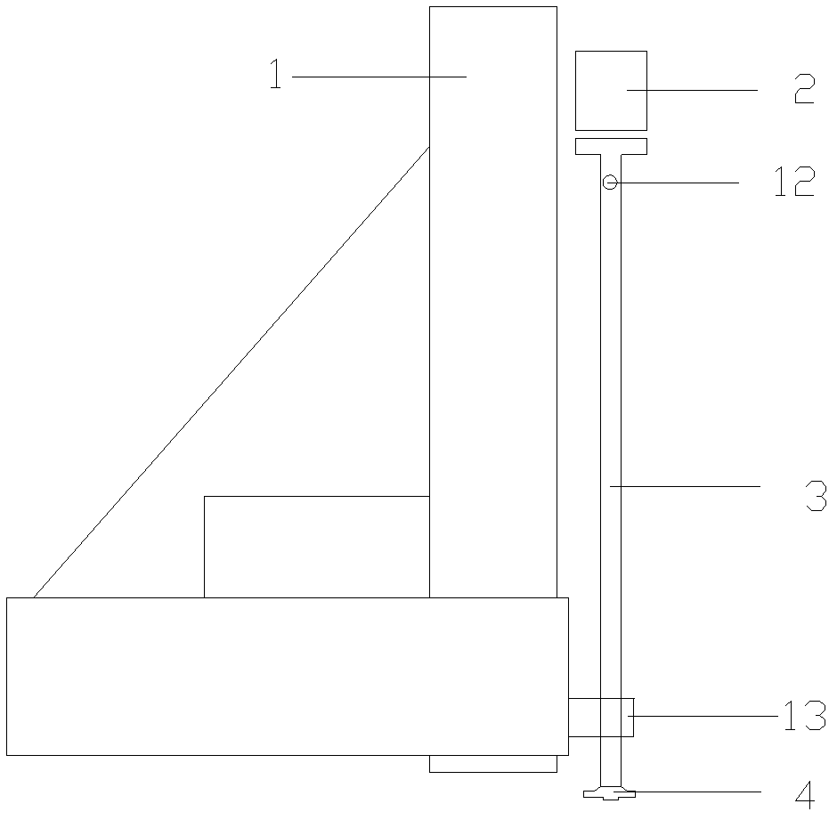
[0061] 1) First, the pile driver 1 is in place, and the vibratory hammer 2, the hole-forming guide rod 3 and the pile head 4 are installed;

[0062] 2) Use the vibrating hammer 2 to move up and down to press the pile head 4 into the soil layer, and pour concrete during the pressing process, so that the concrete top surface continues to maintain the preset elevation according to the construction requirements;

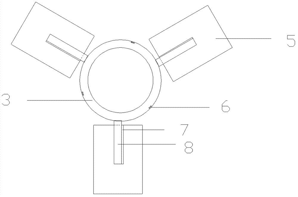
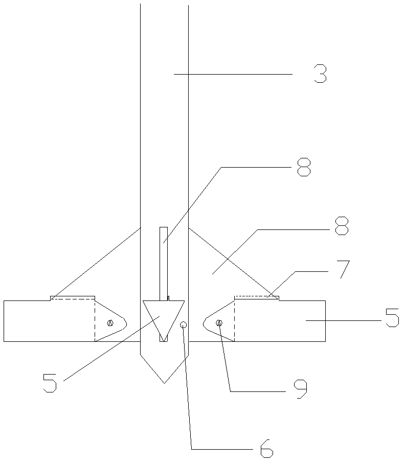
[0063] 3) When the pile head 4 reaches the preset depth required by the construction, open the torsion pump box 13, rotate the hole-forming guide rod 3 and the pile head 4, and make them rotate at a constant speed of 120 degrees; The high-pressure grouting port 12 injects the grout, and the grout is ejected from the grouting port 6 at the bottom of the hole-forming guide rod 3 to form a conical enlarged head at the bottom of the pile;

[0064] 4) A...

Embodiment 2

[0073] A construction technology for pressure-embedded special-shaped cast-in-situ piles, comprising the following steps:

[0074] 1) First, the pile driver 1 is in place, and the vibratory hammer 2, the hole-forming guide rod 3 and the pile head 4 are installed;

[0075] 2) Use the vibrating hammer 2 to move up and down to press the pile head 4 into the soil layer, and pour concrete during the pressing process, so that the concrete top surface continues to maintain the preset elevation according to the construction requirements;

[0076] 3) When the pile head 4 reaches the preset depth required by the construction, open the torsion pump box 13, rotate the hole-forming guide rod 3 and the pile head 4, and make them rotate at a constant speed of 120 degrees; The high-pressure grouting port 12 injects the grout, and the grout is ejected from the grouting port 6 at the bottom of the hole-forming guide rod 3 to form a conical enlarged head at the bottom of the pile;

[0077] 4) A...


PUM


Abstract

The invention discloses a construction process of a pressing-and-embedding special-shaped cast-in-place pile. In the construction process, a pile head is pressed into stratum by a guide rod to a preset depth in a vibrating or static pressure manner, concrete is cast in a bore while pressing during the pressing process, and a concrete surface is maintained at a set height; pressing is stopped whenthe pile head is pressed to the preset depth, the pile head is rotated for a certain angle through the guide rod, high-pressure concrete slurry is jetted from a side nozzle of a swivel head during rotating, so that a complete disc-shaped expanded bore pile is formed at a pile bottom; and then the pile head is lifted out through the guide rod, all branches of the pile head shrink downwards during the lifting process of the pile head, thereby the concrete in the bore can be prevented from being affected. When bore forming is finished, the plain concrete pile body can be directly used as a composite foundation according to specific design requirements; when the plain concrete pile body needs to be used as a reinforced concrete pile, a reinforcement cage of a shape corresponding to the section shape of the pile body is manufactured according to the section shape of the pile body and is pressed in the pile body to form a reinforced concrete cast-in-place pile. The invention also discloses equipment used in the process.

Description

technical field [0001] The invention relates to a construction technology of cast-in-situ piles, in particular to a construction technology and equipment for pressing and embedding special-shaped cast-in-situ piles. Background technique [0002] In foundation engineering, cast-in-situ pile is a widely used form of pile foundation. It has the characteristics of no noise, no vibration, etc., and has little impact on the environment, and can form piles such as large-diameter and super-long piles. The above These advantages make cast-in-situ piles generally optimistic about the development prospects in engineering. [0003] The pile-forming techniques commonly used at the present stage include mud-walled cast-in-place piles, rotary-dug bored piles, impact-holed cast-in-place piles, long auger drilled grouted piles, and post-grouting construction techniques. This type of pile body is a circular pile body, and its bearing capacity is mainly provided by pile side friction resistan...

Claims


Application Information

Patent Timeline
Patent Type & Authority Patents(China)
IPC IPC(8): E02D5/36E02D7/18E02D5/72
Inventor 杨庆义李志亮郑假余边磊亓乐
Owner SHANDONG ELECTRIC POWER ENG CONSULTING INST CORP
Why Eureka
Try Eureka