Absorption-type chemical energy storage device containing crystals
What is Al technical title?
Al technical title is built by PatSnap Al team. It summarizes the technical point description of the patent document.
A chemical energy storage and absorption technology, which is applied to adsorption machines, machine operation, refrigeration and liquefaction, etc., can solve the problems of abnormal operation of absorption units, no measures to dissolve crystallization, and easy occurrence of crystallization risks. The effect of reducing the risk of crystallization, improving energy storage density and energy efficiency, and improving energy storage density
Inactive Publication Date: 2012-01-04
TSINGHUA UNIV
View PDF9 Cites 12 Cited by
Summary
Abstract
Description
Claims
Application Information
AI Technical Summary
This helps you quickly interpret patents by identifying the three key elements:
Problems solved by technology
Method used
Benefits of technology
Problems solved by technology
However, this technical solution still has the following deficiencies: ① Due to the high concentration of the concentrated solution outlet of the generator, after further cooling by the solution heat exchanger, the outlet of the solution heat exchanger is prone to the risk of crystallization, which will cause the absorption unit to malfunction ② the concentrated solution tank can only store solution, and there is no effective crystal melting measure after it is used to store crystals; ③ there is still a large room for improvement in energy storage density; Utilize space; ⑤The device can only realize two operating modes of energy release and energy storage
Method used
Image
Click on the blue label to locate the original text in one second.
Reading with bidirectional positioning of images and text.
Examples
Embodiment Construction
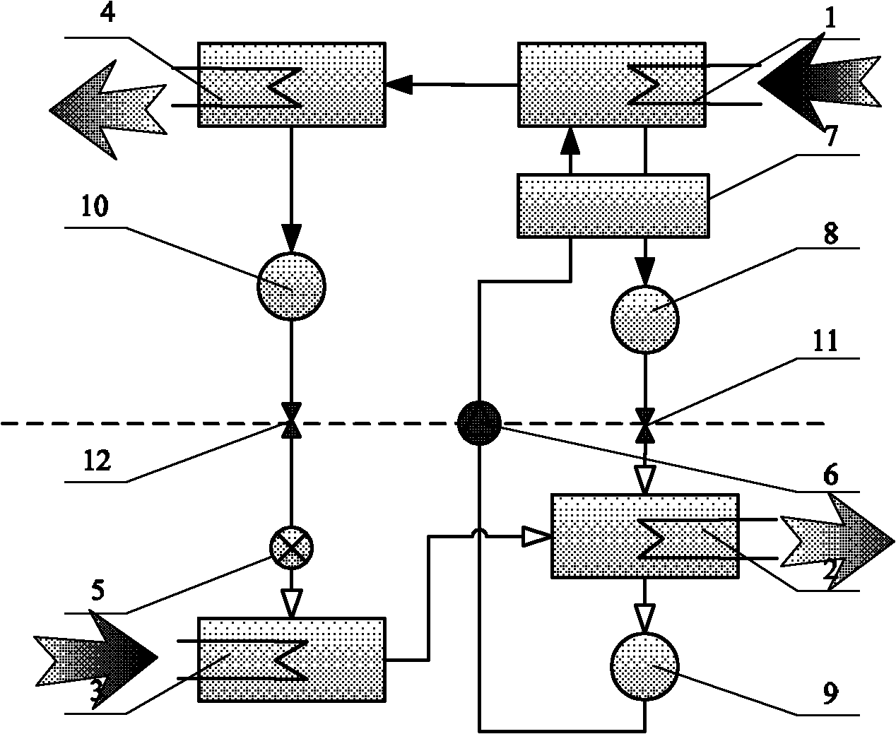
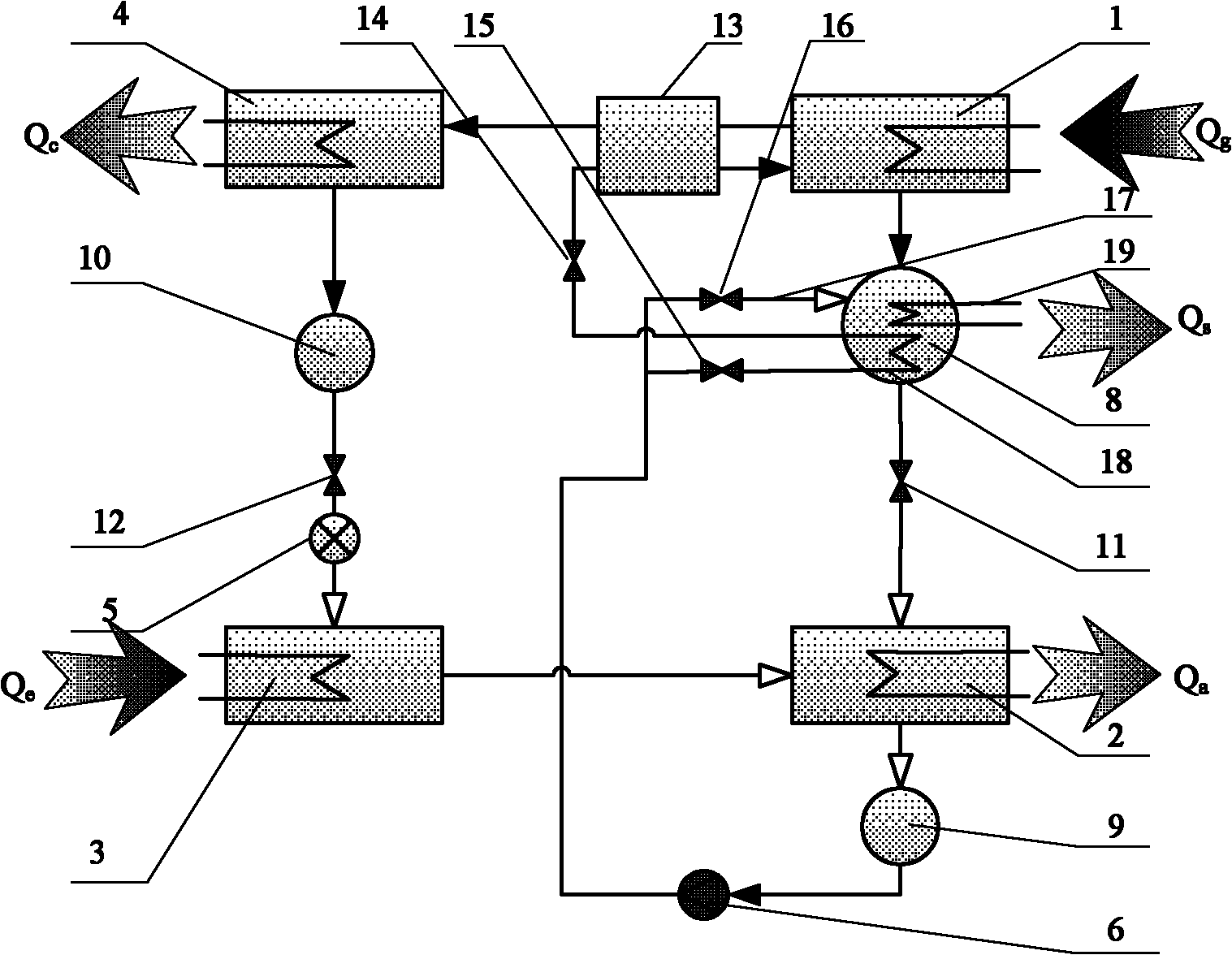
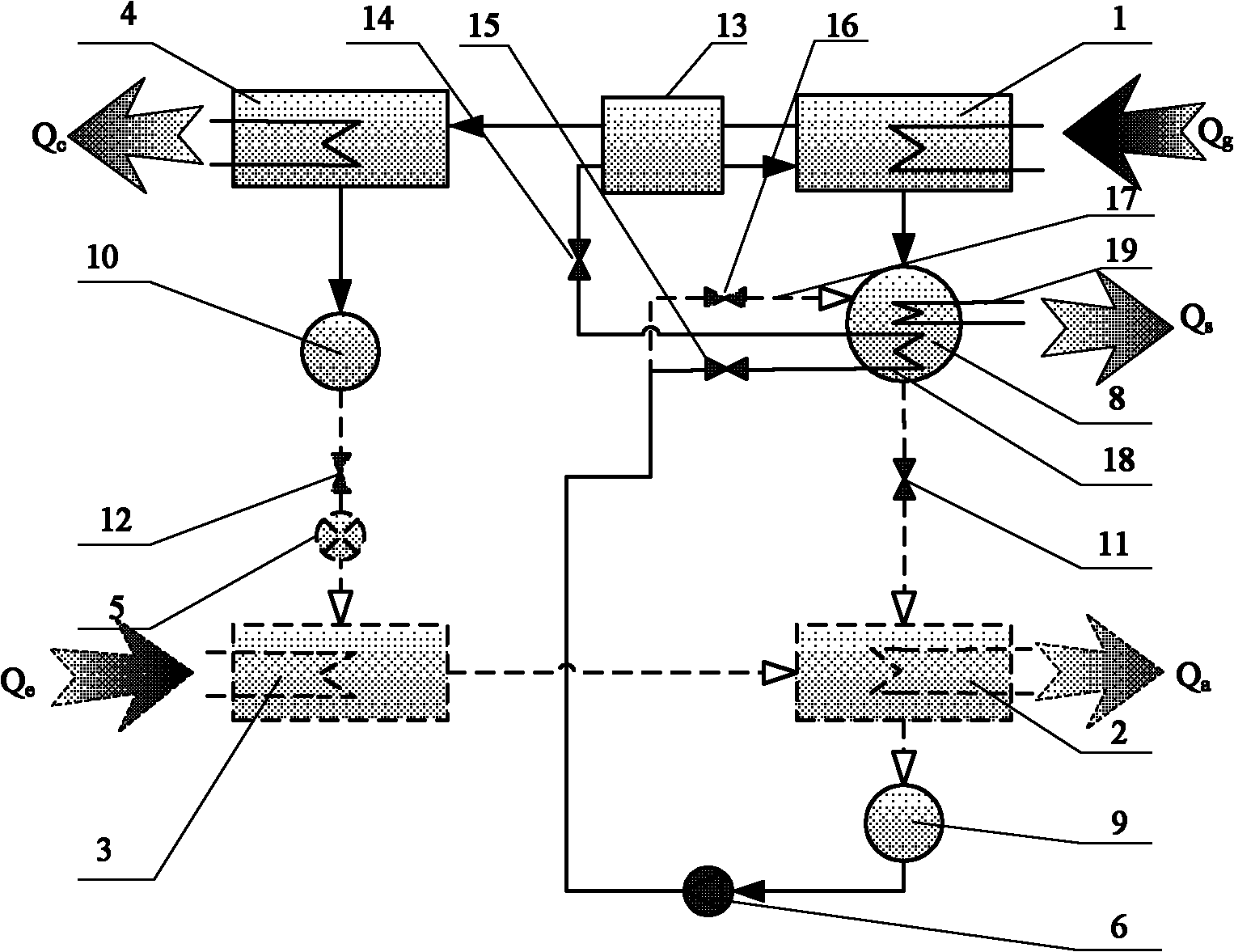
[0021] figure 2 A schematic diagram of the structure of an absorption chemical energy storage device containing crystals of the present invention is given. The chemical energy storage device containing crystals is characterized in that it contains a generator 1, an absorber 2, an evaporator 3, and a condenser 4. Throttle valve 5, solution pump 6, concentrated solution storage tank 8, dilute solution storage tank 9, gas-liquid heat exchanger 13 and refrigerant storage tank 10; the concentrated solution storage tank 8 is provided with a melting tube 17 inlet, and a solution heat exchange tube 18 is provided inside it; the concentrated solution outlet of the generator 1 is connected to the concentrated solution storage tank 8, the absorber 2 and the dilute solution storage tank 9 through pipelines; the steam outlet of the generator 1 The gas-liquid heat exchanger 13, the condenser 4, the refrigerant storage tank 10, the throttle valve 5, the evaporator 3 and the absorber 2 are c...
PUM
Abstract
The invention discloses an absorption-type chemical energy storage device containing crystals. The device comprises a generator, an absorber, an evaporator, a condenser, a throttle valve, a solution pump, a concentrated solution storage tank, a dilute solution storage tank, a gas and liquid heat exchanger, a refrigerant storage tank and the like, wherein a solution heat exchange pipe and a cooling coil pipe are arranged in the concentrated solution storage tank; and an anti-crystallinic pipe is bypassed outside the solution heat exchange pipe for dissolving the crystals. The energy storage device disclosed by the invention can convert solar energy, industrial residual heat, sufficient electrical quantity and the like into chemical energy to be stored, and the mismatching of space, time and amount between a source side and an user side is solved; the energy storage technology can be used for changing defects into benefits, energy storage is carried out by utilizing an absorbent crystallization phenomenon, and the energy storage density is improved; anti-crystallinic measures are disclosed, and the normal operation of energy storage and release is ensured; the system circulation form is improved, the step heat energy utilization is realized, and the utilization efficiency of heat sources is improved; and functions of the device are expanded, so that four modes, namely energy storage, energy release, direct energy supply and simultaneous storage and release, are realized.
Description
technical field [0001] The invention is an absorption chemical energy storage device containing crystals, which relates to the field of adjusting and controlling the system capacity by using chemical energy storage, and particularly relates to the utilization of renewable energy such as solar energy and geothermal energy, waste heat recovery, and combined cooling, heating and power supply systems and other fields, belonging to the field of refrigeration and air conditioning equipment. Background technique [0002] Energy storage technology is a means to solve the mismatch between energy supply and demand in terms of time, space and intensity to improve energy utilization, and it is also an important energy-saving method. As renewable energy such as solar energy with great development potential in the future, due to its periodic, random, low-density, and low-grade energy supply characteristics, energy storage technology will play a vital role in its utilization. Among variou...
Claims
Application Information
Patent Timeline
Application Date:The date an application was filed.
Publication Date:The date a patent or application was officially published.
First Publication Date:The earliest publication date of a patent with the same application number.
Issue Date:Publication date of the patent grant document.
PCT Entry Date:The Entry date of PCT National Phase.
Estimated Expiry Date:The statutory expiry date of a patent right according to the Patent Law, and it is the longest term of protection that the patent right can achieve without the termination of the patent right due to other reasons(Term extension factor has been taken into account ).
Invalid Date:Actual expiry date is based on effective date or publication date of legal transaction data of invalid patent.