Back plate system

A backplane and single board technology, applied in the field of communication, can solve the problems of high implementation cost, increased system power consumption, increased power consumption, etc., and achieve the effect of reducing production cost and improving the bandwidth of the backplane

Active Publication Date: 2012-01-04
ZTE CORP
View PDF4 Cites 45 Cited by
  • Summary
  • Abstract
  • Description
  • Claims
  • Application Information

AI Technical Summary

Problems solved by technology

[0008] a. Increasing the number of high-speed links will bring the following problems: (1), increasing the number of high-speed links on the backplane of the same size will increase the number of layers of the high-speed link backplane, which will increase The processing difficulty of the large backplane leads to an increase in production cost and potential electromagnetic compatibility problems; (2), increasing the number of high-speed links will bring about an increase in power consumption, which will have a great impact on the heat dissipation capability of the system and the packaging technology of the chip. big test
[0009] b. Improving the transmission rate of the high-speed link on the backplane will bring the following problems: there are some essential shackles (such as loss, crosstalk, reflection and parasitic effects, etc.) that prevent the high-speed link from reaching a higher rate. The active signal compensation technology of the external chip is used to improve the signal integrity problem, which will also increase the power consumption of the system. Moreover, even if the active signal compensation technology is used to compensate the signal, the compensation effect is still limited. It will also limit the upper limit that the high-speed link can achieve
This method does not need to embed the optical waveguide on the backplane by setting the optical waveguide channel, but it still needs to embed the optical waveguide on the front and rear boards that form the opposi...

Method used


Image

  • Back plate system
  • Back plate system
  • Back plate system

Examples


Embodiment Construction

[0037] Hereinafter, the present invention will be described in detail with reference to the drawings and examples. It should be noted that, in the case of no conflict, the embodiments in the present application and the features in the embodiments can be combined with each other.

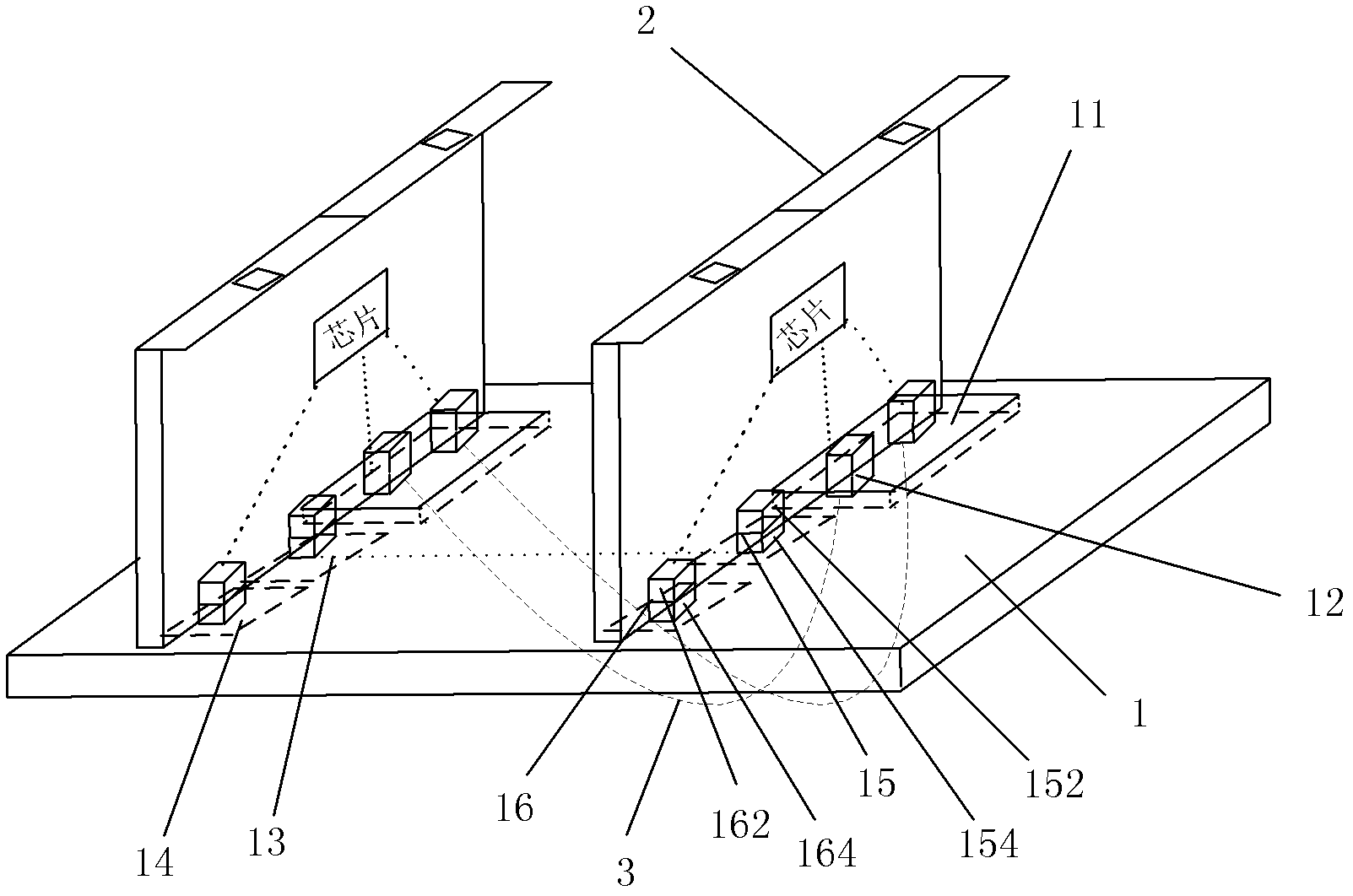
[0038] Please also refer to image 3 , Figure 4 , image 3 is a schematic structural diagram of a backplane system according to an embodiment of the present invention, such as image 3 As shown, the backplane system mainly includes: an electrical backplane body 1, a plurality of single boards 2 and active parallel optical cables 3, wherein each single board 2 is provided with one or more 3 high-speed electrical connectors 12, the electrical backplane body 1 includes one or more high-speed signal connection opening areas 11 for the high-speed electrical connectors 12 to penetrate, and the high-speed electrical connectors on two adjacent single boards 2 12 are connected by an active parallel optic...


PUM


Abstract

The invention discloses a back plate system which comprises an electrical back plate body, a plurality of single plates and active parallel optical cables, wherein each single plate is provided with one or more high speed electric connectors used for adapting the active parallel optical cables, the electrical back plate body comprises one or more high speed signal connection opening areas used for extension of the high speed electric connectors, and the high speed electric connectors on two adjacent single plates are connected through the active parallel optical cables. Through the back plate system, exchange bandwidth of a traditional back plate is increased.

Description

technical field [0001] The present invention relates to the communication field, in particular to a backplane system. Background technique [0002] With the popularization of smartphone terminals and the emergence of emerging technologies such as cloud computing, Internet services have an increasing demand for bandwidth. However, the current port access bandwidth and backplane switching bandwidth of communication devices at the core nodes of the Internet topology are gradually increasing. Therefore, communication equipment (for example, high-end routers) urgently need to update and upgrade the backplane bandwidth to adapt to the new Internet business expansion requirements. [0003] At present, there are two mainstream technologies for improving the bandwidth of communication equipment backplanes: the first type is on traditional electric backplanes ( figure 1 A schematic diagram of the principle of a traditional electric backplane is shown) to increase the number of high-s...

Claims


Application Information

Patent Timeline
IPC IPC(8): H04L12/56H04L12/02
Inventor 王琛严亮夏庆过乾李伟
Owner ZTE CORP
Why Eureka
Try Eureka