Inkless ecological hot baking printing method and printing head device
A printing head and thermal baking technology, which is applied in the fields of technology, printing, and decorative art for producing decorative surface effects, can solve problems such as environmental pollution, and achieve the effects of eliminating environmental pollution, simple structural procedures, and convenient use and management
- Summary
- Abstract
- Description
- Claims
- Application Information
AI Technical Summary
Problems solved by technology
Method used
Image
Examples
Embodiment 2
[0069] Embodiment 2 Contact thermal baking printing method (principle-based example)
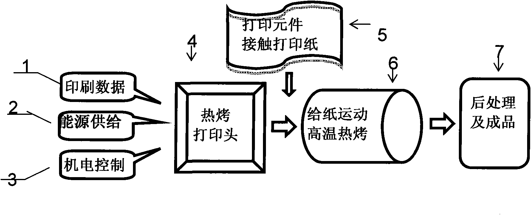
[0070] The process flow of the contact thermal baking printing method is as follows: figure 1 shown. It inherits the basic flow of printing data transmission 1, energy supply 2, electromechanical control system 3, printing head 4, printing head movement process 5, printing paper (paper feeding device) 6, etc. in the current printing method. But innovations were made to the print head. It includes: the heating process of the heating element, the action process of the relevant parts that contact the printing paper, and the process of discoloring the surface of the printing paper through high temperature to form characters or patterns. Printheads can be divided into two categories, they are respectively based on the printheads of existing dot matrix printers and thermal printers, by adding high-temperature thermistors and temperature control devices, etc., and then carrying out corresponding ...
Embodiment 3
[0071] Embodiment 3 A collectively heated needle-type thermal baking print head device
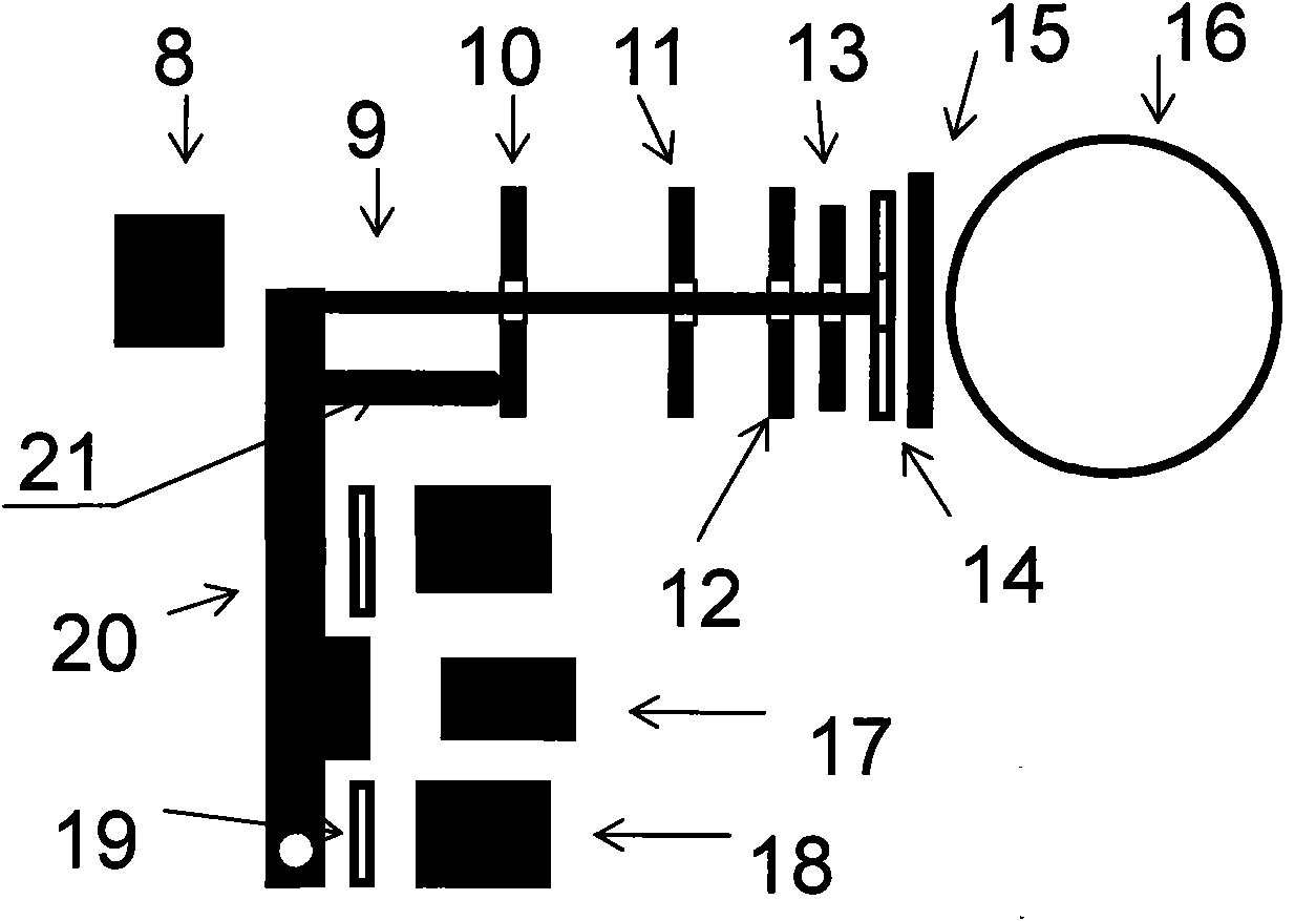
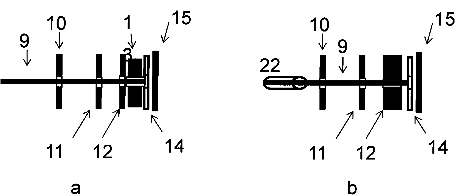
[0072] Figure 7 Shown is a structural schematic diagram of the core part of a collectively heated double-circle pin type thermal baking print head device. Its basic structure and principle are similar to Figure 4 The improvement of the double-circle dot print head of b is as follows: firstly, in terms of materials, it needs to be made of high-temperature-resistant materials; secondly, Figure 4 As shown in a, when the printing needle passes through the positioning plate 10 from the root, it directly passes through the position of the center of the corresponding small hole of the positioning plate, without contacting the positioning plate-current printers need to pass through contact, so that if Figure 5 The needles shown in a were originally arranged in a circle, through Figure 5 The guidance of the positioning plate or guide plate from top to bottom shown in c, finally forming two ...
Embodiment 4
[0073] Figure 8 Shown is a structural schematic diagram of the core part of a double-circle needle type thermal printing head device for each printing needle. Its basic structure and principle are similar to Figure 7 , the improvement is: replace the collective heating plate 13 with the heat insulating plate 12, each printing needle can be heated by electrifying itself, and then according to the printing data information, heat the printing needle that needs to be printed, and let it complete the printing at the same time action. At this time, the temperature of the non-printing printing needles will drop greatly, so compared with the way of collective heating, the heat insulation requirements will be lower. When not printing, there needs to be a certain distance between the tip of the needle tip and the printing paper, usually 0.2-1mm.
PUM
 Abstract
Description
Claims
Application Information
 - R&D
- Intellectual Property
- Life Sciences
- Materials
- Tech Scout
- Unparalleled Data Quality
- Higher Quality Content
- 60% Fewer Hallucinations
Browse by: Latest US Patents, China's latest patents, Technical Efficacy Thesaurus, Application Domain, Technology Topic, Popular Technical Reports.
© 2025 PatSnap. All rights reserved.Legal|Privacy policy|Modern Slavery Act Transparency Statement|Sitemap|About US| Contact US: help@patsnap.com


