
Acoustic emission signal sensing system based on fiber Bragg grating

An acoustic emission signal and sensing system technology, which is applied in the use of acoustic emission technology for material analysis, the use of wave/particle radiation, and the measurement of ultrasonic/sonic/infrasonic waves, etc., can solve the problem of the lack of overall sensing system design and hardware and software. , poor anti-vibration ability, short transmission distance and other problems, to achieve the effect of light weight, fast response speed and high sensitivity

Inactive Publication Date: 2012-01-11
BEIHANG UNIV +2
View PDF8 Cites 34 Cited by
  • Summary
  • Abstract
  • Description
  • Claims
  • Application Information

AI Technical Summary

Problems solved by technology

Existing acoustic emission detection systems such as Chinese patents CN101561420A "intelligent acoustic emission continuous monitor", CN101446507 "USB2.0 multi-channel acoustic emission detection system", CN2724019 "an earthquake and landslide monitoring system based on acoustic emission", etc. The acoustic emission sensors used in the acoustic emission detection system are all based on piezoelectric ceramic materials, which have large volume, narrow frequency band, poor anti-vibration ability, short transmission distance, can only be installed on the surface of the test piece and cannot be exposed to electromagnetic interference, high temperature, etc. Disadvantages such as use in harsh environments such as corrosion
Chinese patent CN1818625A "Fiber Bragg Grating Acoustic Emission and Temperature Sensor" simply expounds the idea of ​​using fiber Bragg gratings to make acoustic emission sensors, but does not design the overall sensing system and realize software and hardware from the perspective of engineering application

Method used


Image

  • Acoustic emission signal sensing system based on fiber Bragg grating
  • Acoustic emission signal sensing system based on fiber Bragg grating
  • Acoustic emission signal sensing system based on fiber Bragg grating

Examples


Embodiment Construction

[0018] The present invention will be further described below in conjunction with accompanying drawings and examples, and the following examples are used to illustrate the present invention, but are not used to limit the scope of the present invention.

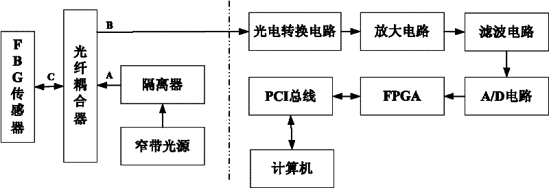
[0019] Such as figure 1 As shown, the present invention includes a fiber Bragg grating sensing part (to the left of the dotted line) and a signal processing part (to the right of the dotted line). The fiber grating sensor senses the acoustic emission signal and converts the wave signal into an optical signal. Among them, the A port of the Y-type fiber coupler is connected to the light source, the B port is connected to the photoelectric conversion circuit of the signal processing part, and the C port is connected to the FBG sensor. The signal processing part demodulates and converts the received optical signal, and then analyzes and processes the signal data by FPGA. Specifically, it is composed of FBG sensor, fiber optic cou...


PUM


Abstract

The invention provides an acoustic emission signal sensing system based on fiber Bragg grating (FBG). The system comprises a fiber grating sensing unit and a signal processing unit; the fiber grating sensing unit comprises an FBG sensor, a light source, an isolator and a Y-type fiber coupler; the signal processing unit comprises a photoelectric switching circuit, an amplification circuit, a filter circuit, an A / D circuit and an FPGA (field-programmable gate array); the FBG sensor is firmly fixed in a packaging material, and a couplant is added between the packaged FBG sensor and a member to be detected. The system provided in the invention has the following advantages: a wide detection frequency band, detection scope being in a range of 50 KHz to 300 KHz; high sensitivity, strain resolution being 2 (mu epsilon) microstrani; a fast response speed more than 10 MHz; a long transmission distance which enables long distance between a detection spot and a monitoring spot to be feasible thanks to low loss transmission of fibers; strong capability in resisting electromagnetic interference, vibration, dampness, corrosion, etc., which enables the system to be used normally for a long time in a severe environment. A sensor made of fibers in the invention has the advantages of light weight, small volume, good imbedibility, etc.

Description

technical field [0001] The invention relates to an acoustic emission signal sensing system based on a fiber Bragg grating, and belongs to the technical field of acoustic emission detection. Background technique [0002] As the embodiment of the country's comprehensive strength and military strength, aviation aircraft plays an increasingly important role in modern warfare. It plays an increasingly important role in early warning, reconnaissance, anti-tank, air defense, electronic warfare, and air command systems. Aircraft has become the most important weapon for gaining the initiative in war, and will have an important and even decisive impact on the course and outcome of the war. However, because the structure of the aircraft is very precise and complex, it often works in various harsh environments, as well as flying at hypersonic speeds, etc., resulting in an increased probability of failure, such as cracks in parts, corrosion, structural fractures, etc., these The process...

Claims


Application Information

Patent Timeline
IPC IPC(8): G01N29/14G01H9/00
Inventor 魏鹏李宁刘奇隋青美梅盛开李成贵孙志平
Owner BEIHANG UNIV
Learn More