Method for welding substrate and diaphragm of diaphragm-moving polymer microfluidic chip

A technology of microfluidic chip and welding method, which is applied in the direction of welding equipment, laser welding equipment, chemical instruments and methods, etc.

Active Publication Date: 2012-01-18
BEIJING BOHUI INNOVATION TECH
View PDF7 Cites 11 Cited by
  • Summary
  • Abstract
  • Description
  • Claims
  • Application Information

AI Technical Summary

Problems solved by technology

[0007] The technical problem to be solved by the present invention is: how to realize the firm welding between the substrate and the diaphragm of the membrane-moving polymer microfluidic chip, and the welding surface is flat and uniform

Method used


Image

  • Method for welding substrate and diaphragm of diaphragm-moving polymer microfluidic chip
  • Method for welding substrate and diaphragm of diaphragm-moving polymer microfluidic chip
  • Method for welding substrate and diaphragm of diaphragm-moving polymer microfluidic chip

Examples


Embodiment 1

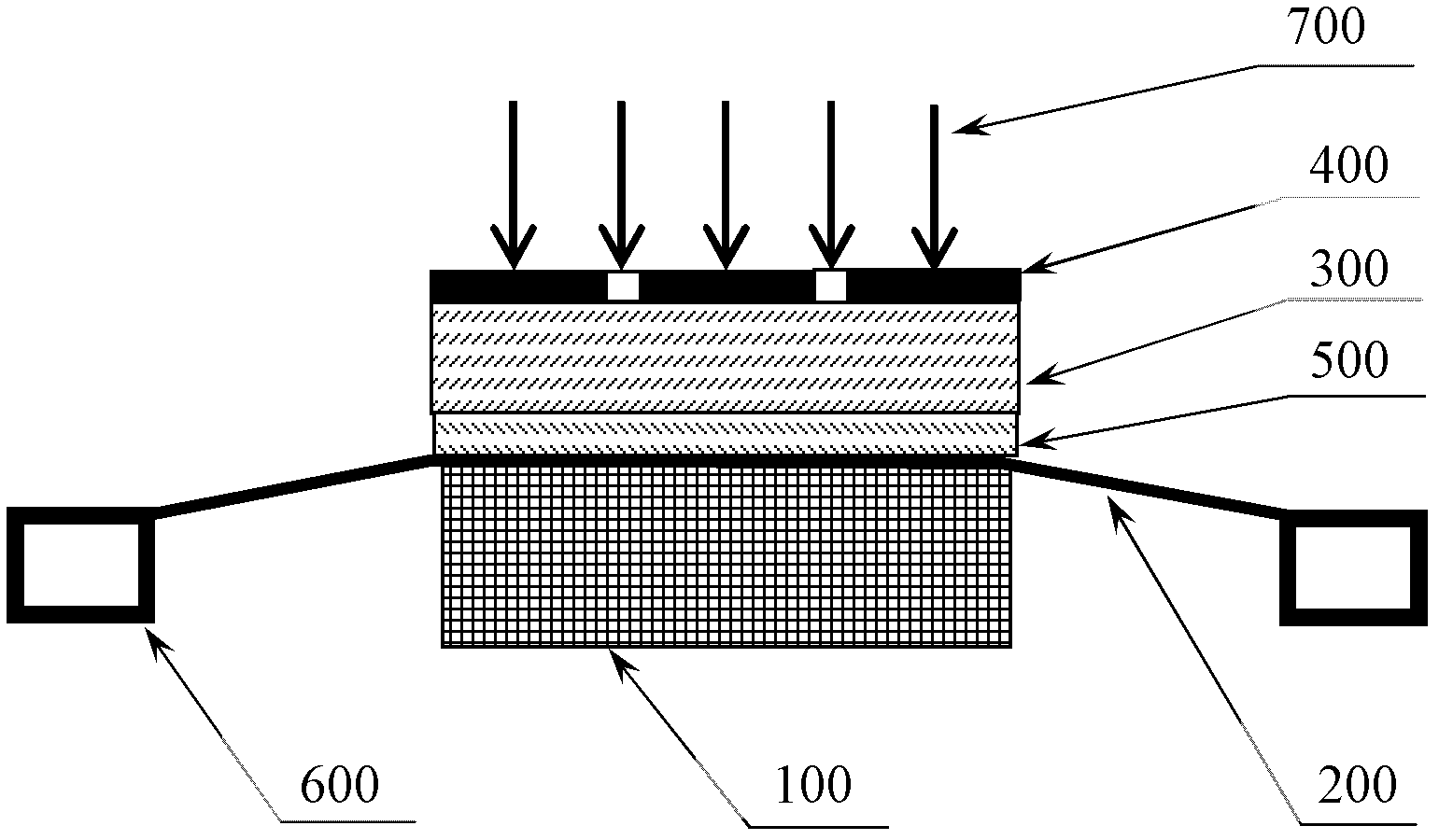
[0045] This embodiment provides a method for welding the substrate and diaphragm of a membrane-moving polymer microfluidic chip, such as figure 1 Shown is a schematic diagram of the welding structure using the welding method in this embodiment. Before welding, the substrate 100 is fixed, the diaphragm 200 is covered on the surface of the substrate 100, and pressure is applied to press the diaphragm 200 on the surface of the substrate 100. In this embodiment, a transparent pressure plate 300 is used to apply pressure to the diaphragm.

[0046]Preferably, in order to make the welding firm, a tensioning device 600 is used to apply a certain tension to the diaphragm 200 , and the stretched diaphragm 200 covers the surface of the substrate 100 . When the pressure is applied, the tension is adjusted according to the elastic parameters of the diaphragm 200 and the applied pressure. Since the diaphragm 200 is tightened, the substrate 100 bears against the diaphragm 200 from below, so ...

Embodiment 2

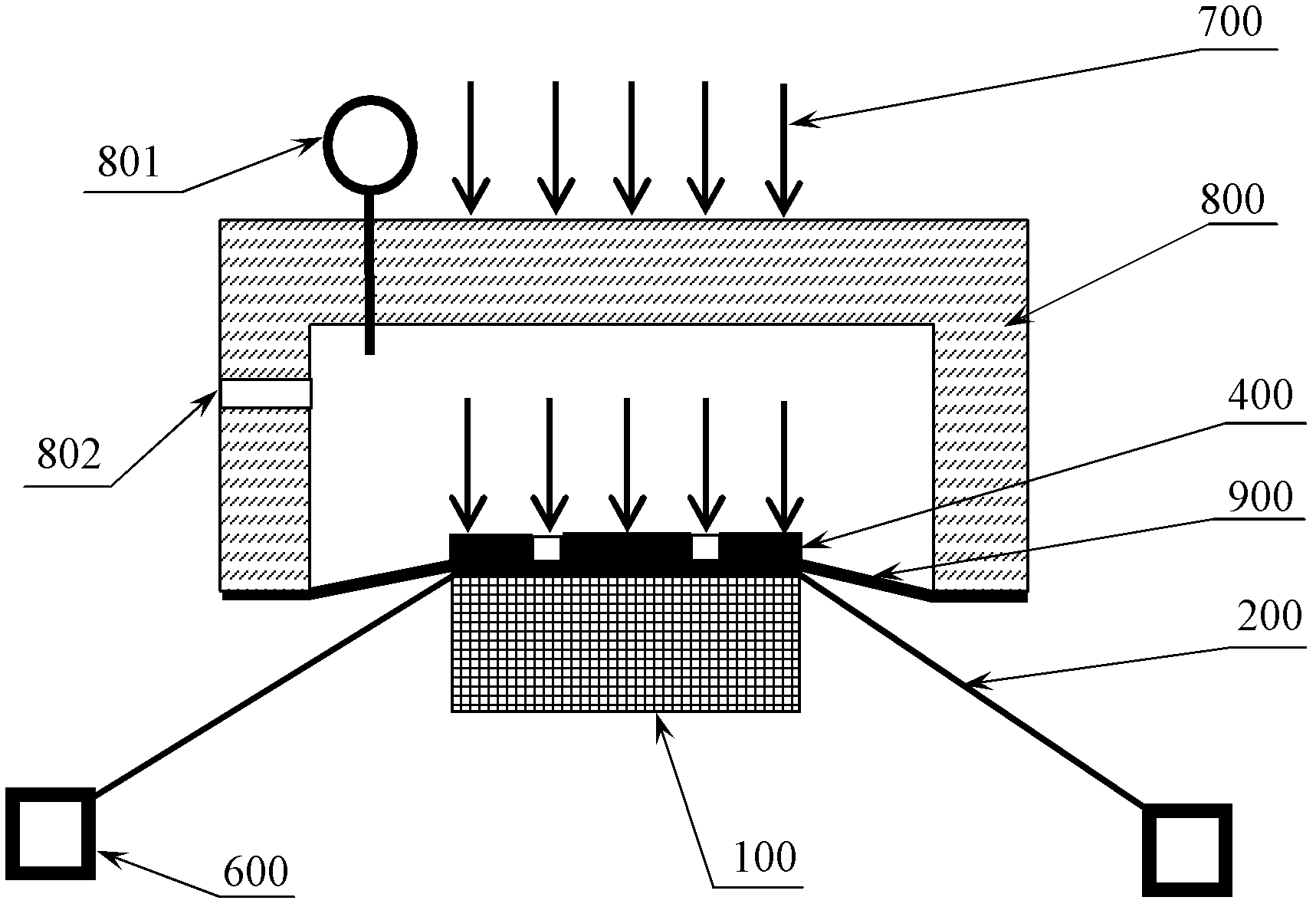
[0051] This embodiment provides a method for welding the substrate and diaphragm of a membrane-moving polymer microfluidic chip, such as figure 2 Shown is a schematic diagram of the welding structure using the welding method in this embodiment. The welding steps are basically the same as in Embodiment 1, the difference is the way of applying pressure to the diaphragm 100 . In this embodiment, pressure is applied to the diaphragm 100 by means of air pressure-compression film. Before welding, the substrate 100 is fixed, and the diaphragm 200 covers the surface of the substrate 100 . Preferably, the tensioning device 600 is used to stretch the diaphragm 200 to cover the surface of the substrate 100 . The barometric chamber 800 and pressure film 900 are placed on the surface of the diaphragm 200 , the pressure film 900 seals the barometric chamber 800 in advance, and the body of the barometric chamber 800 is provided with a pressure sensor 801 and a control valve 802 . When ap...

Embodiment 3

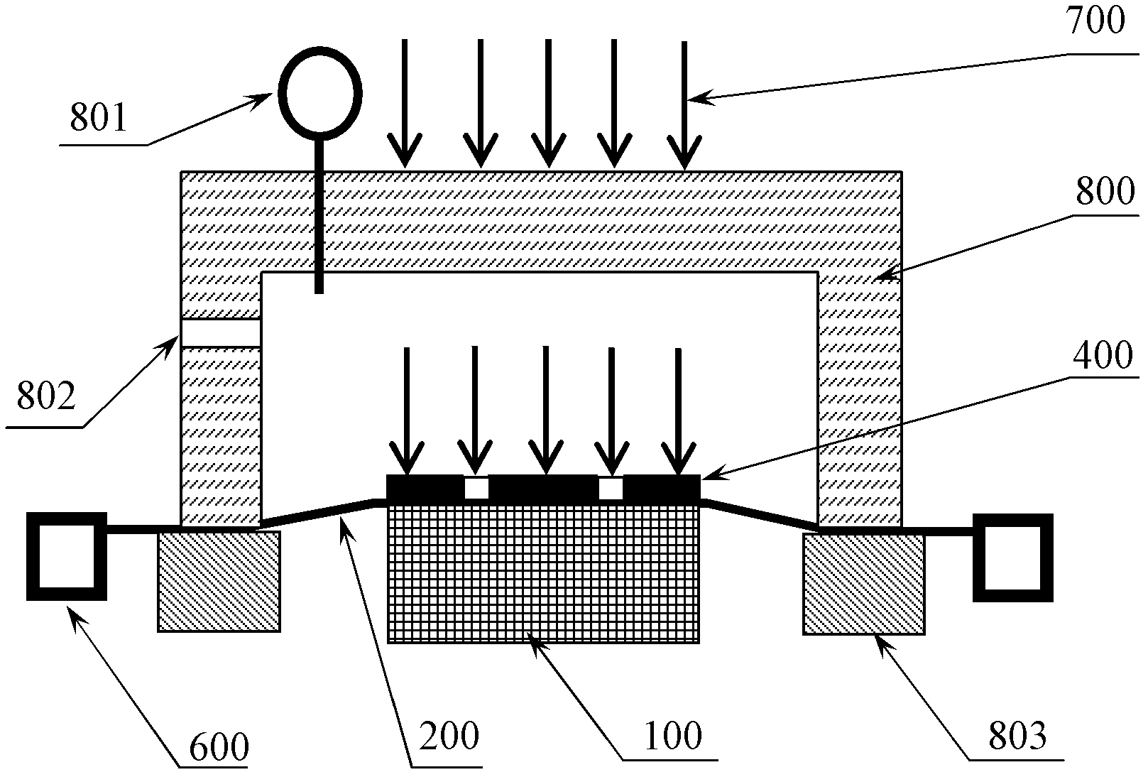
[0058] Such as image 3 As shown, the welding method of the substrate and diaphragm of the membrane-moving polymer microfluidic chip provided in this embodiment is basically the same as that of Embodiment 2, the difference is that the pressure chamber 800 is not sealed with a pressure film, but the substrate 100 and the diaphragm are placed After 200 minutes, the diaphragm 200 is pressed tightly around the air pressure chamber 800 through the sealing seat 803 matched with the air pressure chamber 800 to seal the air pressure chamber 800 . Preferably, before sealing, the tensioning device 600 is used to apply tension to the diaphragm 200 to make it tight. The way of applying pressure is the same as in Example 2.

[0059] Preferably, when inflated, the tensile force is adjusted according to the elastic parameters of the diaphragm 200 and the air pressure, so as to control the tensile deformation and ensure the welding quality. In this embodiment, since the diaphragm 200 is use...


PUM


Abstract

The invention discloses a method for welding a substrate and a diaphragm of a diaphragm-moving polymer microfluidic chip, which relates to the technical field of diaphragm-moving polymer microfluidic chip production. The method includes the steps that: before welding, the substrate is fixed, the diaphragm is spread flat to cover the surface of the substrate; pressure is applied to press the diaphragm on the surface of the substrate; during welding, laser is utilized to irradiate the welding area on the substrate via the diaphragm, and after the welding area is heated to be molten, the substrate and the diaphragm are welded together. The method realizes the welding of the diaphragm and the substrate of the diaphragm-moving polymer microfluidic chip, moreover, welding is firm, and the face of weld is smooth and even.

Description

technical field [0001] The invention relates to the technical field of manufacturing a membrane-moving polymer microfluidic chip, in particular to a method for welding a substrate and a diaphragm of a membrane-moving polymer microfluidic chip. Background technique [0002] The manufacturing method and device of membrane-moving polymer microfluidic chips are the key to realizing industrial scale production of microfluidic technology and entering the application market. Laser radiation fusion welding is used to weld polymers to improve welding accuracy and quality, and micro-welding can be performed processing. [0003] The Chinese invention patent "Laser welding method and device for welding plastic workpieces or plastics and other materials ZL00101924.4" discloses a method of laser welding plastic workpieces, which is to press two workpieces to be welded together, and the welding surfaces are in contact , the workpiece close to the laser is transparent to the laser, and the...

Claims


Application Information

Patent Timeline
Patent Type & Authority Applications(China)
IPC IPC(8): B23K26/20B23K26/42B29C65/16
CPCB81B2203/0127B29L2031/756B29C66/9241B01L2200/0689B29C66/939B29C66/9221B01L2300/044B81B2201/058B29C66/244B29C65/1654B81C3/001B29C65/1696B29C66/242B29C66/81267B29C66/81455B29C66/9161B29C66/53461B23K26/42B01L2300/0816B29C66/919B29C65/16B29C66/344B23K26/20B01L3/502707B01L3/00B81C2203/036B29C65/1635B29C66/1122B29C66/7392B29C66/82421B29C66/82423B29C66/8266B29C66/82661B29C66/8322B29C66/934B29C66/961
Inventor 杨奇
Owner BEIJING BOHUI INNOVATION TECH
Why Eureka
Try Eureka