Forming method of trackless lampshade and forming mould

A molding method and molding die technology, applied in the field of lighting equipment, can solve the problems of unavoidable welding points, material strength reduction at welding lines, large flow resistance, etc. uniform effect

Inactive Publication Date: 2012-01-18
XIAMEN HONTAY INDAL
View PDF3 Cites 1 Cited by
  • Summary
  • Abstract
  • Description
  • Claims
  • Application Information

AI Technical Summary

Problems solved by technology

But it is contrary to expectations, because each part of the blow molding product has a certain inflation ratio, in order to reduce the feed point, local non-inflation is a way, but the result of local cold drawing and inflation is to affect the light flux and the appearance color of the product is not good. uniform
Therefore, the manufacturer adopted the reform of the mold and changed the feed point to a position on the side. In this way, the tube embryo looks beautiful when it is not blown, but once it is blown, it is found that the feed point Flow marks and color spots appear on the weld line of the opposite material when light passes through, and even cracks will appear at the weld line of the material during blow molding
This is because, in injection molding, after the molten material is injected into the cavity of the mold, the farther away from the injection port and the closer to the wall of the cavity, the faster the material cools, and the faster the flow rate drops. The flow process of hot material pushing cold material is formed in the cavity; and because the wall thickness of the product is required to be uniform after blow molding, the wall thickness of the injection molded tube embryo is usually uneven, and the flow resistance is greater in the thinner part of the injection mold cavity, which is relatively thick. The flow resistance of the thick part is small, so the forward speed of each point of the injection front is different, and the stroke of each point of the injection front from the injection port to the mold parting surface is also different, so the resistance is greater and the stroke is longer. Before the front material reaches the parting surface, it will be surrounded by the front material at the faster flow rate, and the gas in the encirclement cannot be discharged (the vent hole is generally set at the parting surface of the mold), and gas accumulation will be formed. As a result, the pressure is increased due to the accumulation of gas, the temperature is increased due to the increased pressure, and the material is yellowed or burnt due to the temperature increase, and finally the strength of the material at the weld line formed after the front material is surrounded and encircled is reduced (the formation process of the front material welding like figure 1 shown), so that after blowing, flow lines and color spots or even cracks will appear at the weld line
In addition, the Chinese invention patent application with the publication number CN1198125A discloses a molding method of annular feeding from the side of the product. Although this method can avoid weld lines, it cannot avoid the formation of weld points by encircling and enclosing each other with the front materials, and for For non-revolving products, welding lines cannot be avoided
[0004] To sum up, the quality of LED lampshade, whether it is appearance or internal quality, always leaves a regret for LED lighting manufacturers.

Method used


Image

  • Forming method of trackless lampshade and forming mould
  • Forming method of trackless lampshade and forming mould
  • Forming method of trackless lampshade and forming mould

Examples


Embodiment Construction

[0020] The present invention will be further described in detail below in conjunction with the accompanying drawings and specific embodiments.

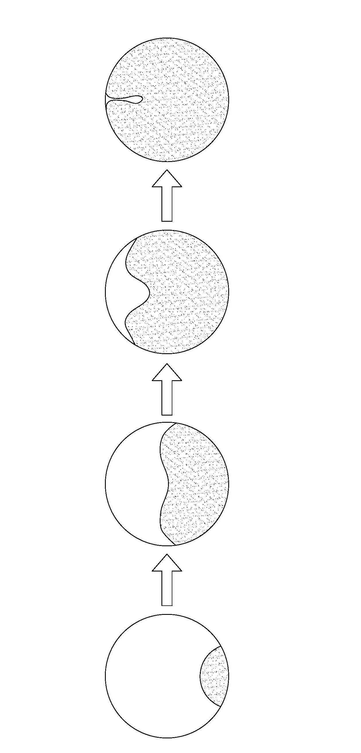
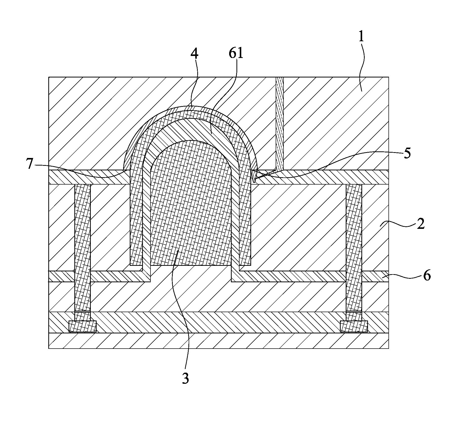
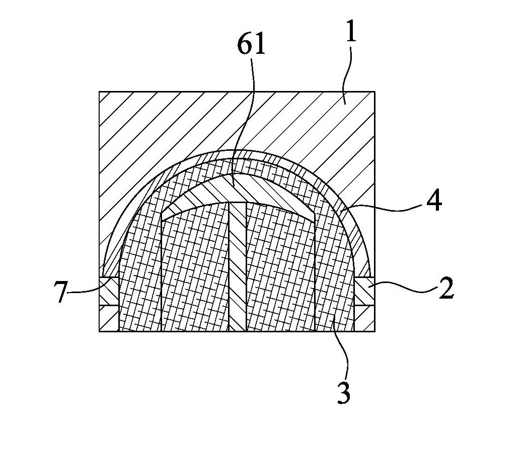
[0021] The invention discloses a method for forming a seamless lampshade. The steps of the method are: setting a cavity in the mold in the shape of the opposite injection part, using the edge of the opening of the opposite injection part as the parting surface, and A feed inlet is set at a certain position, and the melted material is injected into the cavity of the mold from the feed inlet. During the injection process, the cavity is locally heated. The heating position is at the point where the forward resistance of the material is the largest. When the forward resistance is the same, then At the point where the front material travels the longest from the feed port to the parting surface, the front material in all positions is gathered at the parting surface, and finally forms a seamless injection part. The molding process of injecti...


PUM


Abstract

The invention discloses a forming method of a trackless lampshade. The method comprises the following steps of: arranging a cavity corresponding to the shape of a cast in a mould; taking the opened edge of the corresponding cast as a parting surface to arrange a charge hole at a certain position of the parting surface; injecting a molten casting material in the cavity of the mould through the charge hole; locally heating the cavity in the injection process, wherein the heating position is a position with highest advance resistance of a forward material; and, when advance resistances are same, the heating position is the longest stroke from the charge hole to the parting surface of the forward material, therefore, the forward materials in all positions are collected on the parting surface; and finally, obtaining the trackless cast. By using the method disclosed by the invention, all the forward materials of the casting material can be finally collected on the parting surface of the mould, therefore, any casting point, fusion welding line or fusion welding point cannot be formed on the cast; and the trackless lampshade can be completely formed. The invention further discloses a forming mould of the trackless lampshade.

Description

technical field [0001] The invention relates to the technical field of lighting equipment, in particular to a forming method and a forming mold of a traceless lampshade. Background technique [0002] At present, there are three kinds of production technologies applied to the lampshades used in LED lighting lamps, one is "one-step molding" (injection mold blow molding); blow molding); the third is injection molding. [0003] At present, the lampshades produced by the above-mentioned technologies generally have two major defects. First, the injection molded lampshade has a single shape, which cannot meet diverse needs. Second, lampshades similar to spherical shapes and mushroom bulbs must be formed by blow molding. However, the blow-molded lampshades currently used in the market are all injection molded in the middle, that is to say, their "feed point" is located at the vertex of the product's symmetry axis, and the "feed point" generated during molding has become the first...

Claims


Application Information

Patent Timeline
Patent Type & Authority Applications(China)
IPC IPC(8): B29C45/00B29C45/73B29C45/26B29L22/00
Inventor 张力泰
Owner XIAMEN HONTAY INDAL
Why Eureka
Try Eureka