

Method for producing o-nitroaniline by multiple series-connected kettles
A technology of o-nitroaniline and multiple reactors in series, applied in the field of ammoniation, can solve the problems of short residence time, difficult control, and high energy consumption of pipeline reactors, and achieve the advantages of reducing residence time, increasing overall volume, and prolonging residence time. Effect
- Summary
- Abstract
- Description
- Claims
- Application Information
AI Technical Summary
Problems solved by technology
Method used
Image

Examples
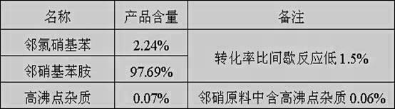
Embodiment 1
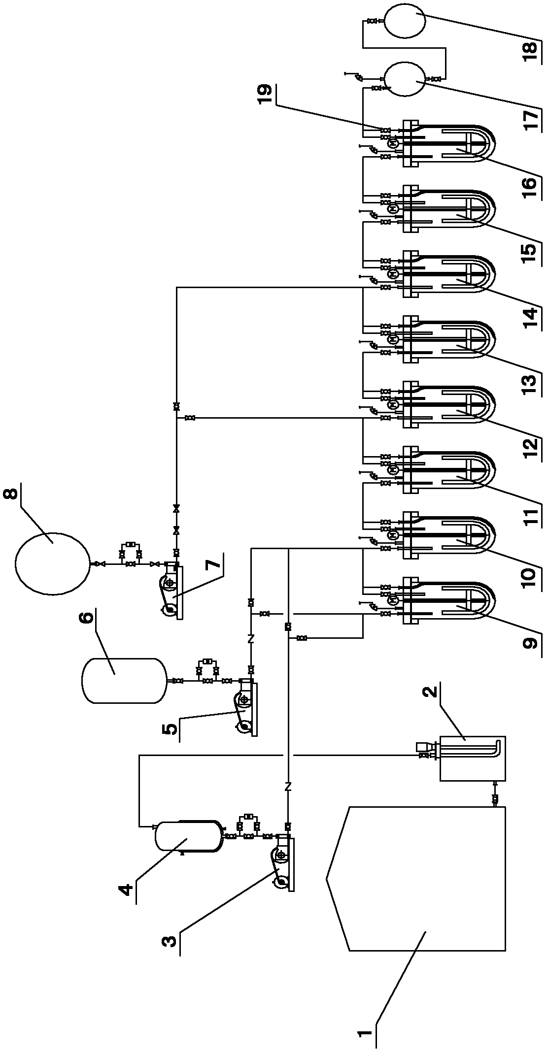
[0030] (1) First, add ammonia water with a mass percentage concentration of 37.5% and o-chloronitrobenzene into eight ammoniated autoclaves connected in series at a volume ratio of 1:1, and the materials in each ammoniated autoclave reach the volume of the autoclave When the temperature is 50%, stop feeding, and heat up each hydrogenation autoclave until the temperature rises above 165°C to allow the materials in each ammoniation autoclave to undergo ammoniation reaction.
[0031] (2) Use the discharge valve to control the pressure of the ammoniated autoclave in the system. When the system pressure reaches 4.0-4.5Mpa and 185-195°C, use a pressure pump to add ammonia water and o-chloronitrobenzene at a rate of 2m3 / h. For the first ammoniated autoclave and the second ammoniated autoclave, use the feed regulating valve to control the volume ratio of the feed amount of the first ammoniated autoclave to the second ammoniated autoclave to be 1:3, and use a pressure pump to pump the l...
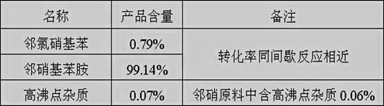
Embodiment 2
[0039](1) First, add ammonia water with a mass percentage concentration of 38.5% and o-chloronitrobenzene into eight ammoniated autoclaves in series at a volume ratio of 1:1, and the materials in each ammoniated autoclave reach the volume of the autoclave When the temperature is 50%, stop feeding, and heat up each hydrogenation autoclave until the temperature rises above 165°C to allow the materials in each ammoniation autoclave to undergo ammoniation reaction.
[0040] (2) Use the discharge valve to control the pressure of each ammoniated autoclave in the system. When the system pressure reaches 4.0-4.5Mpa and 185-195°C, use a pressure pump to pump ammonia water and o-chloronitrobenzene at a rate of 2.4m3 / h Add to the first ammoniated autoclave and the second ammoniated autoclave, use the feed regulating valve to control the volume ratio of the feed amount of the first ammoniated autoclave and the second ammoniated autoclave to 1:4, and use a pressure pump to Liquid ammonia i...
PUM
 Abstract
Description
Claims
Application Information