Multi-section foundation of wind driven generator weathered rock

A wind power generator, multi-section technology, applied in infrastructure engineering, buildings, sheet pile walls, etc., can solve the problems of natural environment damage, waste of raw materials and funds, damage to rock formations, etc., to achieve simple operation and reduce damage degree, the effect of bearing capacity improvement

Inactive Publication Date: 2012-01-18
孟庆波
View PDF5 Cites 2 Cited by
  • Summary
  • Abstract
  • Description
  • Claims
  • Application Information

AI Technical Summary

Problems solved by technology

[0002]Currently, the current technology uses wind turbine foundations such as Figure 1, the fan is installed on a large cap platform made of concrete and steel bars through the flange, and the diameter of the large cap platform can reach 15-30 meters, with a height of 3-5 meters, which requires about 300-500 cubic meters of concrete and steel pouring, which not only wastes raw materials and funds; at the same time, it also destroys a large area of ​​rock formations, causing damage to the natural environment

Method used


Image

  • Multi-section foundation of wind driven generator weathered rock
  • Multi-section foundation of wind driven generator weathered rock
  • Multi-section foundation of wind driven generator weathered rock

Examples


Embodiment 1

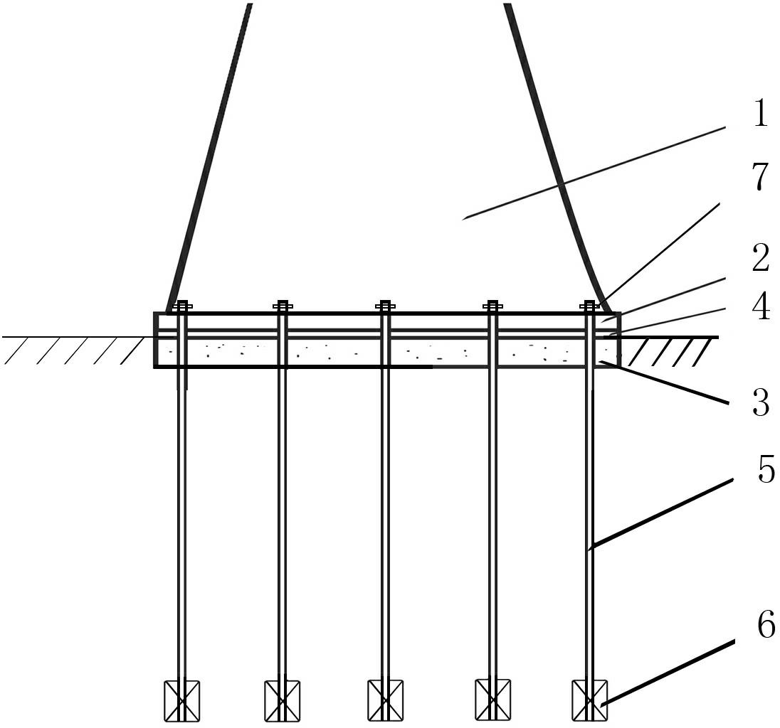
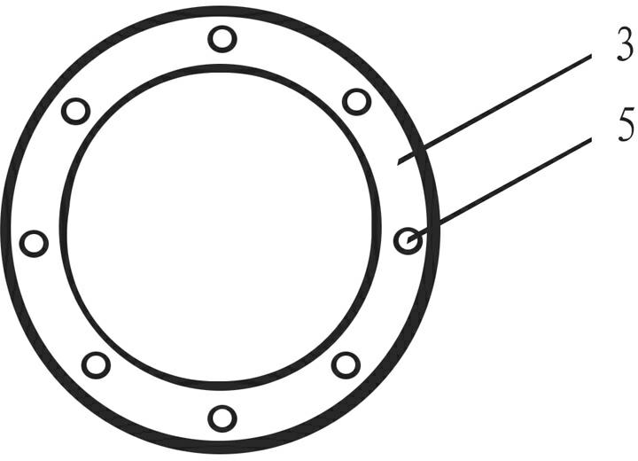
[0022] like Figure 2-Figure 3 as shown, figure 2 It is a structural schematic diagram of the present invention, image 3 It is a top view of the bearing platform in the present invention.

[0023] The present invention is a multi-section foundation of weathered rock formations for wind power generators. It is a foundation method in which a fan flange 2 is fixedly connected to the bottom of the fan cylinder 1, and the foundation flange 4 on the concrete bearing platform 3 and the fan flange 2 are firmly connected by bolts. Lan 4 is located above ground level. A plurality of anchor rods 5 are connected by nuts 7 through the foundation flange and the fan flange. One week of bearing platform 3 is vertically provided with a plurality of anchor rods 5, and the bottom of expanded bottom anchor rod 5 is provided with diameter-expanding cylinder 6.

[0024] During concrete implementation, 40 anchor rods can be established.

Embodiment 2

[0026] The bottom expansion anchor rod 5 of the present invention is arranged inclined outwards, and its inclination can be 10 degrees, 15 degrees, 20 degrees, 25 degrees...60 degrees.

[0027] There is no flange on the concrete cap 3, only a screw is provided on the concrete cap 3, and the bolts on the flange 2 of the fan base can be directly connected through nuts. Others are the same as implementation example 1.

Embodiment 3

[0029] like Figure 4 as shown, Figure 4 It is a structural schematic diagram of another embodiment of the present invention.

[0030] Both the middle part and the bottom of the expanded bottom anchor rod 5 according to the present invention are provided with enlarged diameter cylinders 6 to resist the horizontal thrust. Others are the same as implementation example 1.


PUM


Abstract

The invention belongs to the technical field of power transmission line anchoring foundations and particularly relates to a multi-section foundation, which is applied to wind driven generator foundations in rock and weathered rock areas. A fan flange is arranged at the bottom of a fan drum; a foundation flange on the upper part of a bearing platform is connected with the fan flange; and a plurality of anchoring rods are connected through the bearing platform. Because the anchoring rods are arranged on the bearing platform and can be vertically arranged as well as obliquely arranged outwards, the anchoring effect of the foundation can be greatly improved and the bearing capacity is obviously improved; because a flange plate is arranged on the bearing platform, the multi-section foundation has the characteristic of simple and feasible operation, and because the bearing platform occupies a relatively small space, the damage degree to rocks can be greatly reduced, the design requirement on the bearing capacity can be met only by casting concrete of a small bearing platform, and wastes of fund and raw materials are also greatly reduced. Therefore, the multi-section foundation can be applied to various wind driven generator foundations in the rock and weathered rock areas and has higher practicability.

Description

technical field [0001] The invention belongs to the technical field of anchoring foundations for wind power generators, in particular to a weathered rock layer multi-section foundation for wind power generators, which is used for wind power generator foundations in rocks and weathered rock areas. Background technique [0002] At present, the current technology uses wind turbine foundations such as figure 1 As shown, the fan is installed on a large cap platform made of concrete and steel bars through the flange. The large cap platform can reach a diameter of 15-30 meters and a height of 3-5 meters, requiring about 300-500 cubic meters A large amount of concrete and steel bars are poured, which not only wastes raw materials and funds; at the same time, it also destroys a large area of ​​rock formations, causing damage to the natural environment. Contents of the invention [0003] Aiming at the problems existing in the above-mentioned prior art, the present invention provid...

Claims


Application Information

Patent Timeline
Patent Type & Authority Applications(China)
IPC IPC(8): E02D27/44E02D5/74E02D27/32
Inventor 孟庆波王芝茗缪军曲忠侃王豹詹俊桥
Owner 孟庆波
Why Eureka
Try Eureka