Multi-rotor wind power generation system with tail vane

A wind power generation system, multi-rotor technology, applied in the direction of wind power generators, wind power generator components, wind power generation, etc. in the same direction as the wind, can solve the problem of restricting the use of giant wind power units, land transportation, difficulty in installation, and difficulty in hoisting and dismantling and other issues, to achieve the effect of increasing the total installed capacity, facilitating integration, modularization and scale, and mature manufacturing technology

Active Publication Date: 2012-01-18
TIANJIN UNIV
View PDF3 Cites 5 Cited by
  • Summary
  • Abstract
  • Description
  • Claims
  • Application Information

AI Technical Summary

Problems solved by technology

Once a problem occurs, the wind farm will cause economic losses due to downtime and power outages, plus the cost of maintenance, hoisting and replacement parts, over-limit transportation, repeated installation, etc. In addition, most of the wind turbines are installed in remote or inaccessible areas, so it is difficult to hoist and disassemble Big, huge price paid in the end
Therefore, although the manufacturing cost of wind turbines decreases with the increase of power, the total cost will increase on the contrary considering the maintenance and other costs in the later period.
On the other hand, the length of blades of giant wind turbines will reach 60-70m, and land transportation and installation are extremely difficult. The capacity of cranes used for installation will exceed 1200-1400t. Many areas do not have this condition, thus limiting the use of giant wind turbines

Method used


Image

  • Multi-rotor wind power generation system with tail vane
  • Multi-rotor wind power generation system with tail vane
  • Multi-rotor wind power generation system with tail vane

Examples


Embodiment Construction

[0030] The implementation of the present invention will be described in further detail below in conjunction with the accompanying drawings. The following detailed description is only descriptive, not restrictive, and cannot limit the protection scope of the patent of the present invention.

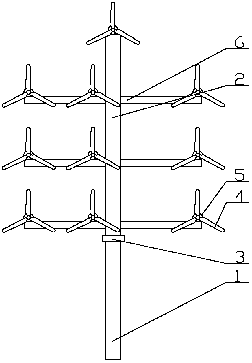
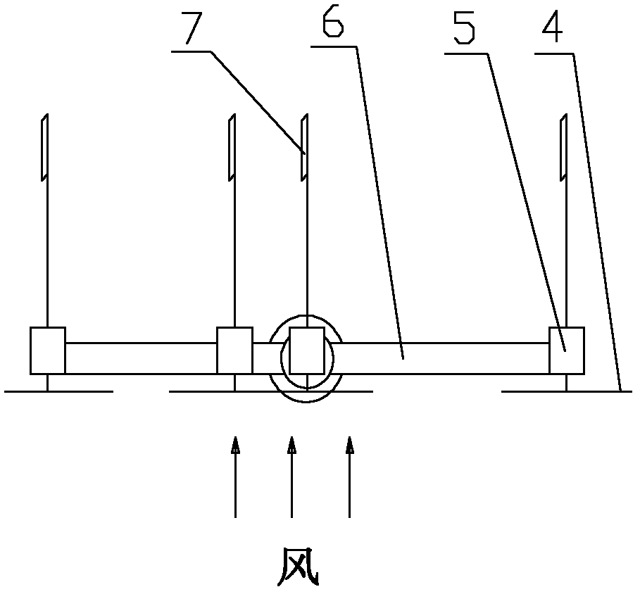
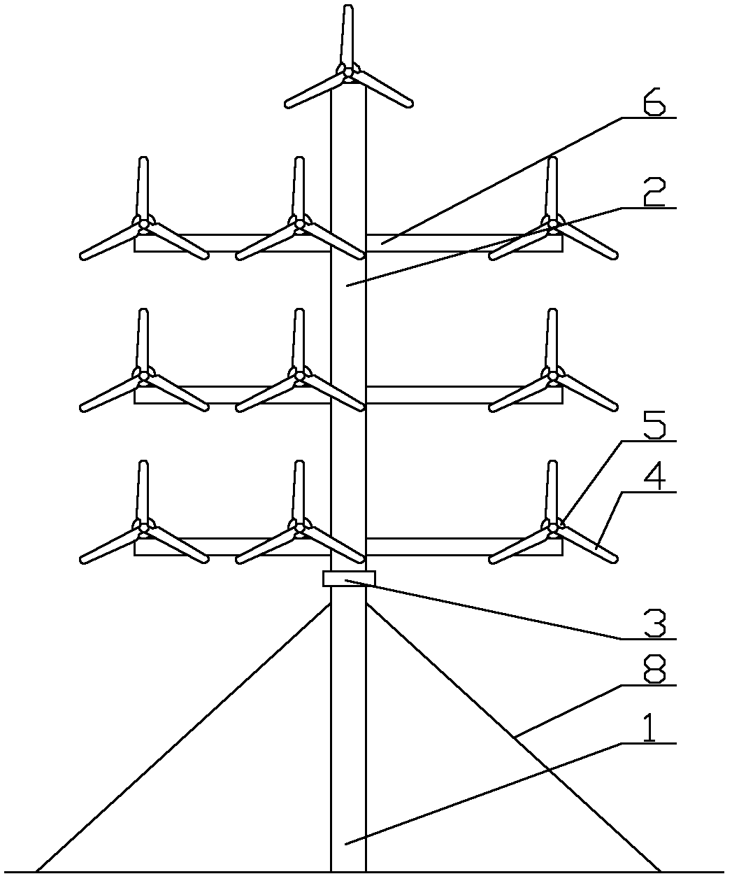
[0031] A multi-rotor wind power generation system with a tail rudder, including a lower tower 1, a slewing bearing 3 and a wind turbine, and an upper tower 2, a beam 6 and a tail rudder 7, and the slewing bearings are arranged on the upper tower and the lower tower Between the frames, one end of the beam is fixedly connected to the upper tower, and the wind turbine is fixedly connected to the top of the upper tower or / and the beam. The wind turbine includes a wind wheel 4 and a nacelle 5. There are 2-100 wind turbines, and the upper tower The lengths of the beams on both sides are equal, the number of wind turbines set on the beam on one side of the upper tower is 1-20 more than the number ...


PUM


Abstract

The invention discloses a multi-rotor wind power generation system with a tail vane, which comprises a lower pylon 1, a rotary bearing 3, windmills, an upper pylon 2, beams 6 and the tail vane 7, wherein the rotary bearing is arranged between the upper pylon and the lower pylon; one end of each beam is fixedly connected with the upper pylon; the windmills are fixedly connected with the top of theupper pylon or / and the beams; each windmill comprises a wind wheel 4 and an engine room 5; the number of the windmills is 2 to 100; the lengths of the beams at two sides of the upper pylon are unequal; the number of the windmills on the beams at one side of the upper pylon is 1 to 20 more than that of the windmills on the beams at the other side of the upper pylon; and the tail vane is connected with the upper pylon, the beams or / and the engine room through a pin roll. The multi-rotor wind power generation system has the advantages of long service life of the vane, small occupied area, low cost for installation and maintenance, favorable reliability, wide application range, automatic wind resistance and yawing and safe protection; and the rotary bearing or a rotary driving device in the engine room is omitted.

Description

technical field [0001] The invention belongs to the field of wind energy utilization, and relates to a multi-rotor wind power generation system with tail rudders. Background technique [0002] With the global energy crisis and global environmental pollution intensifying, many countries are paying more attention to the research, development and utilization of clean and renewable energy. The Global Wind Energy Council pointed out that compared with other renewable energy technologies, wind power technology is more mature, its efficiency is higher, the industry has the best prospect, and its development and utilization growth rate is much higher than that of conventional energy. One of the fastest renewable energy technologies. [0003] The wind rotor is the core component that converts wind energy into mechanical energy, so the performance of the blade determines the performance of the wind turbine, and the safe and stable operation of the blade within the design life is very...

Claims


Application Information

Patent Timeline
Patent Type & Authority Applications(China)
IPC IPC(8): F03D9/00F03D1/02F03D11/00F03D7/04F03D9/25F03D13/20
CPCY02E10/725Y02E10/722Y02E10/723Y02E10/72
Inventor 朱丽王一平黄群武
Owner TIANJIN UNIV
Why Eureka
Try Eureka