Direct driving type wind driven generator with double motors

A wind turbine, direct-drive technology, applied in wind turbine components, wind turbines, wind power generation, etc., can solve the problems of reducing the wind energy utilization rate of the generator, unable to adjust the output of the inner stator, and difficult to obtain wind energy utilization, etc. Improve axial space utilization, improve convenience, and reduce weight

Active Publication Date: 2012-01-18
欣达重工股份有限公司
View PDF7 Cites 9 Cited by
  • Summary
  • Abstract
  • Description
  • Claims
  • Application Information

AI Technical Summary

Problems solved by technology

[0004] 1) Since the structure is supported by double bearings, that is, both ends of the rotating shaft are supported by the casing of the motor, the structure is relatively complicated, and its axial dimension is large;
[0005] 2) For the electric excitation in the composite magnetic field, the rotating shaft needs to be made of non-magnetic steel, such as stainless steel, but the strength of stainless steel is low and the price is expensive. To meet the required strength, the cross-sectional size of the rotating shaft must be increased. Therefore, it will be greatly increased. its cost of manufacture;
[0006] 3) In addition, in order to improve the utilization rate of wind energy, the method of electric excitation is adopted, but electric excitation consumes power, so it will reduce the utilization rate of wind energy of the generator; moreover, electric excitation only works on the external stator motor, so the adjusted It is only the output of the outer stator, but the output of the inner stator cannot be adjusted, so it is difficult to obtain the best utilization of wind energy

Method used


Image

  • Direct driving type wind driven generator with double motors
  • Direct driving type wind driven generator with double motors
  • Direct driving type wind driven generator with double motors

Examples


Embodiment Construction

[0025] The present invention will be described in further detail below in conjunction with the accompanying drawings and specific embodiments.

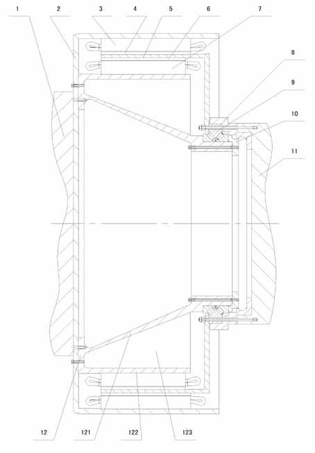
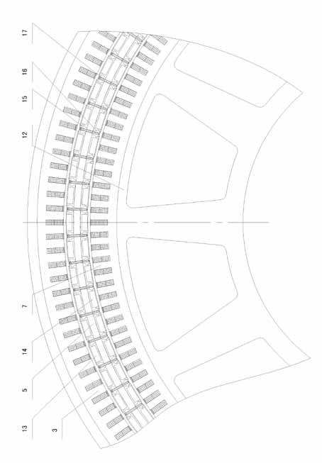
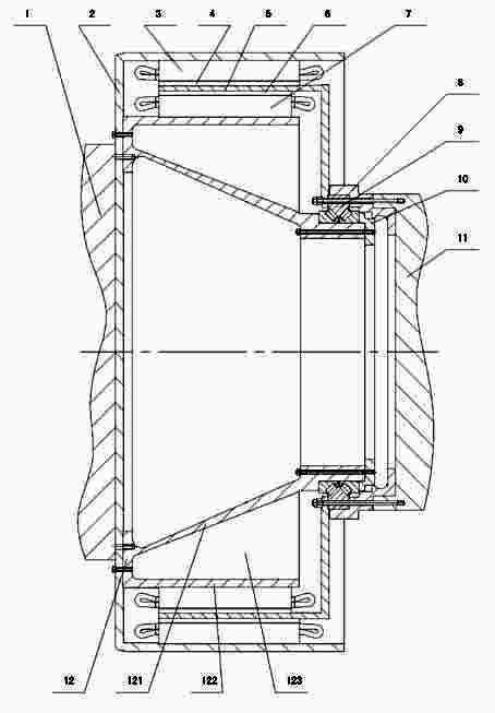
[0026] Depend on figure 1 and figure 2 The structure diagram of the shown dual-motor direct-drive wind power generator of the present invention can be known, and it comprises nacelle 1, machine base 2, impeller 11, main shaft 12, double stator and double rotor, and one end of described machine base 2 is connected with nacelle 1 connection, the double stators and double rotors are located in the base 2. The arrangement order of the double stators and double rotors from outside to inside is the outer stator 3 , the inner rotor 4 , the outer rotor 6 and the inner stator 7 . One end of the main shaft 12 is fixedly connected to the base 2 near the nacelle 1 , and the impeller 11 is rotatably connected to the other end of the main shaft 12 . The generator also includes a rotor support frame 5 , the rotor support frame 5 is fixedly conne...


PUM


Abstract

The invention discloses a direct driving type wind driven generator with double motors, which comprises an engine room (1), an engine base (2), an impeller (11), a main shaft (12), double stators and double rotors, wherein the engine base (2) is connected with the engine room (1); for the double stators and the double rotors, an outer stator (3), an inner rotor (4), an outer rotor (5) and an inner stator (7) are sequentially arranged from outside to inside; one end of the main shaft (12) is fixedly connected with the engine base (2) which is close to one side of the engine room (1); the impeller (11) is connected with the other end of the main shaft (12) in a rotating manner; the generator also comprises a rotor supporting frame (5) which is fixedly connected with the impeller (11); the outer stator (3) is in interference fit with the engine base (2); and the inner stator (7) is in interference fit with the main shaft. After the structure is adopted, as the double motor structure is arranged in the radial direction, the internal space of the motors is fully used, the structure of the generator is not only simplified, but also the axial size of the generator is shortened.

Description

technical field [0001] The invention relates to the field of generators, in particular to a dual-motor direct-drive wind power generator suitable for high power. Background technique [0002] About 80% of the megawatt-level power generators in the prior art are double-fed generators, that is, the wind wheel drives the wind generator to generate electricity through a multi-stage speed increaser. During the operation of the wind turbine, the failure rate of the gearbox is relatively high, generally around 70%. In recent years, in order to solve this problem, a permanent magnet direct-drive wind turbine that does not require a gearbox has been introduced. However, due to the low operating speed of the permanent magnet direct-drive wind turbine (usually lower than 20r / min), the volume of the generator is huge. For example, some 2MW direct-drive wind turbines have a diameter of 5m. However, my country's coastal wind resources are abundant. In order to make full use of offshore ...

Claims


Application Information

Patent Timeline
Patent Type & Authority Applications(China)
IPC IPC(8): F03D11/00H02K16/00H02K1/28F03D80/00F03D80/70
CPCY02E10/722Y02E10/72
Inventor 潘式正
Owner 欣达重工股份有限公司
Why Eureka
Try Eureka