Pulse coding distribution-type fiber Raman and Brillouin scattering sensor

A distributed optical fiber and Brillouin scattering technology, which is applied in the direction of transmitting sensing components, instruments, scientific instruments, etc. by optical devices, can solve the problem of low temperature and strain measurement accuracy, narrow spectral bandwidth, and the inability to simultaneously measure optical fiber strain and temperature To achieve the effect of increasing the signal-to-noise ratio, increasing the number of emitted photons, and improving measurement accuracy

Inactive Publication Date: 2012-01-18
CHINA JILIANG UNIV
View PDF5 Cites 8 Cited by
  • Summary
  • Abstract
  • Description
  • Claims
  • Application Information

AI Technical Summary

Problems solved by technology

[0002]In the field of distributed optical fiber sensors, there are distributed optical fiber Raman scattering photon temperature sensors at home and abroad to detect the temperature on site, and there are distributed optical fiber Brillouin scattering photon sensors abroad The sensor detects the strain and temperature of the field. Due to the cross effect, the strain and temperature of the optical fiber cannot be measured at the same time. The Newson research team of the University of Southampton, UK proposed to use a narrow-band laser light source to measure the temperature by using the back spontaneous anti-Stokes Raman scattering of the optical fiber. And use the spontaneous fiber Brillouin scattering effect to measure strain, but because the spectral bandwidth of fiber Brillouin scattering is very narrow, the accuracy of measuring temperature and strain is low (M.N.Allahbabi, Y.T.Cho and T.P.Newson, Simulataneous Distributed Measurements of Temperature and Strain using Spontaneous Raman and Brillouin Scattering, Optics Letters, 2005, 1 June, p.1276-1278)

Method used


Image

  • Pulse coding distribution-type fiber Raman and Brillouin scattering sensor
  • Pulse coding distribution-type fiber Raman and Brillouin scattering sensor
  • Pulse coding distribution-type fiber Raman and Brillouin scattering sensor

Examples


Embodiment Construction

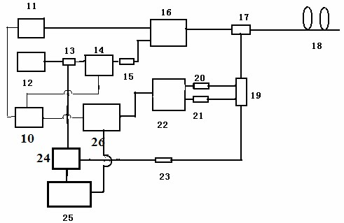
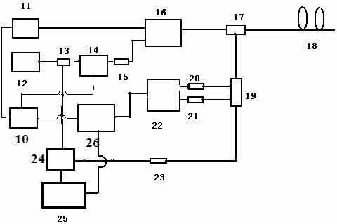
[0035] refer to figure 1 , the pulse-coded distributed optical fiber Raman and Brillouin scattering sensor of the present invention includes a waveform generator 10, a semiconductor FP cavity broadband fiber laser 11, a semiconductor external cavity narrowband pulse fiber laser 12, an optical fiber splitter 13, and pulse coded light modulation device 14, one-way device 15, erbium-doped fiber amplifier 16, bidirectional coupler 17, sensing fiber 18, integrated wavelength division multiplexer 19, first photoelectric receiving and amplifying module 20, second photoelectric receiving and amplifying module 21, direct detection System 22, narrow-band transmission fiber grating 23, circulator 24, coherent detection system 25 and industrial computer 26; the input end of waveform generator 10 is connected with industrial computer 26, and an output end of waveform generator 10 is connected with semiconductor FP cavity broadband optical fiber The input end of laser 11 is connected, and ...


PUM

PropertyMeasurementUnit
wavelengthaaaaaaaaaa

Abstract

The invention discloses a pulse coding distribution-type fiber Raman and Brillouin scattering sensor which comprises a waveform generator, a semiconductor F-P (Fabry-Perot) cavity broadband fiber laser, a semiconductor outer cavity narrow-band pulse fiber laser, a fiber wave separator, a pulse coding photomodulator, an one-way device, an Er-doped fiber amplifier, a bidirectional coupler, a sensing fiber, an integrated wavelength division multiplexer, two photoelectric receiving and amplifying modules, a direct detection system, a narrow-band transmission fiber bragg grating, a circulator, a coherent detection system and an industrial personal computer. The sensor adopts tow laser sources, wherein the semiconductor F-P cavity broadband fiber laser measures temperature by use of a spontaneous fiber Raman scattering intensity ratio; and the other one semiconductor outer cavity narrow-band pulse fiber laser measures strain of frequency shift by use of the spontaneous fiber Brillouin scattering ray. A time sequence codes laser pulse, the spatial resolution is improved by lowering laser pulse width while the transmission photon number is improved, the signal to noise ratio of the systemis improved, and the measurement precision is measured and improved while on-line temperature and strain are realized in space.

Description

technical field [0001] The invention relates to a pulse code distributed optical fiber Raman and Brillouin scattering sensor, belonging to the technical field of optical fiber sensing. Background technique [0002] In the field of distributed optical fiber sensors, there are distributed optical fiber Raman scattering photon temperature sensors at home and abroad to detect the temperature of the scene, and there are distributed optical fiber Brillouin scattering photon sensors abroad to detect the strain and temperature of the scene. Due to the cross effect, they cannot be simultaneously To measure the strain and temperature of the optical fiber, the Newson research team at the University of Southampton proposed to use a narrow-band laser source to measure the temperature using the back spontaneous anti-Stokes Raman scattering of the optical fiber and use the Brillouin scattering effect of the optical fiber to measure the strain. However, due to the The spectral bandwidth of ...

Claims


Application Information

Patent Timeline
Patent Type & Authority Applications(China)
IPC IPC(8): G01D5/353G01B11/16G01K11/32G01K11/322G01K11/324
Inventor 张在宣龚华平余向东王剑锋李裔金尚忠
Owner CHINA JILIANG UNIV
Why Eureka
Try Eureka