Light guide for delivering radiation and method of manufacture

A light guide and optical fiber technology, applied in the field of manufacturing the light guide, can solve the problems of deformation, mechanical strength drop, inability to know, etc.

Inactive Publication Date: 2016-01-20
SCHOTT AG
View PDF8 Cites 0 Cited by
  • Summary
  • Abstract
  • Description
  • Claims
  • Application Information

AI Technical Summary

Problems solved by technology

[0010] However, according to the coupling described in DE 10 2004 006 932 B3 and especially the manufacture of this coupling, there are many drawbacks and doubts about the convertibility
As a rule of thumb, deformation of the optical fiber in direct contact with the extrusion tool can cause major problems
When using extrusion tools without special surface qualities, the fibers are often strongly damaged by deformation of the optical interface, so that the light guidance is extremely limited and a large part of the laser radiation is coupled out of the fiber
Furthermore, it is well known to the person skilled in the art that the adhesion of optical fibers on extrusion tools or even the attachment of metal to glass is to be expected, and furthermore no means for preventing these effects are known from this publication
Furthermore, the mechanical strength of optical fibers is greatly reduced after the thermal reforming process, so that it is not possible to apply the polishing process to single-layer fused fiber ribbons without breaking, as described in the published text, and it is not possible to carry out the necessary polishing process
Therefore, it can be assumed from this that the components described in this text cannot or cannot be produced economically and economically in the manner described

Method used


Image

  • Light guide for delivering radiation and method of manufacture
  • Light guide for delivering radiation and method of manufacture
  • Light guide for delivering radiation and method of manufacture

Examples


Embodiment Construction

[0061] For illustration purposes, only schematic representations are used in the drawings and true dimensional relationships are not reflected to scale. The number of optical fibers is also matched for illustration purposes. Other non-essential elements, such as plug housings, etc., are likewise omitted in the illustration.

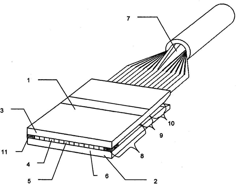
[0062] exist figure 1 The perspective view of the light guide according to the invention shows the coupling-in end (1), the coupling-in end comprising the carrier plate (2), the fiber deformed on the end face (6) of the coupling-in end and positively connected (4,5) and cover plate (3). Spacers ( 11 ) are arranged on both sides of the fibers, and these spacers are in planar contact with the carrier plate and the cover plate after the hot pressing process. These spacers are located laterally of the fiber strip and extend in the direction of the fibers only over the area or partial area of ​​the fusion zone ( 8 ). A transition zone (9) and a lead-out zo...


PUM


Abstract

The invention relates to a light guide for transmitting radiation, in particular of a high-power diode laser, and a method for producing the light guide. The light guide is characterized by a slit-shaped, elongated light entry surface which is formed from one or more layers of optical fibers, wherein the fibers are at least partially connected to one another in a form-fitting manner and to the carrier plate. Furthermore, the invention relates to a method for producing a light guide according to the invention.

Description

technical field [0001] The invention relates to a light guide for transmitting radiation, in particular of a high-power diode laser, and a method for producing the light guide. Background technique [0002] High-power diode lasers usually consist of one or more so-called laser bars, where each laser bar has several emitters with slit-shaped light coupling surfaces arranged side by side along the semiconductor junction at on the laser bar. The individual emitters have a small expansion of only about 1 μm parallel to the semiconductor junction in the direction of the semiconductor junction, ie along the so-called fast axis, and typically 100 to 200 μm in the so-called slow axis. The emitted radiation has a divergence angle of typically 20° to 30° in terms of half angle along the fast axis and a significantly smaller divergence angle of typically 5° along the slow axis. [0003] There is a wide range of prior art techniques for coupling semiconductor laser light into light gu...

Claims


Application Information

Patent Timeline
Patent Type & Authority Patents(China)
IPC IPC(8): G02B6/42G02B6/255G02B6/30G02B6/36H01S5/40
CPCG02B6/2552G02B6/305G02B6/3628G02B6/4202G02B6/4249H01S5/4012H01S5/4031H01S5/02251
Inventor 胡贝图斯·卢瑟尔特
Owner SCHOTT AG
Why Eureka
Try Eureka