
Solar heat transfer unit

A solar energy and heat transfer medium technology, applied in solar thermal devices, solar thermal power generation, heating devices, etc., can solve the problems of difficult practical operation, difficult to guarantee safety, high system cost, no leakage danger, simple driving, The effect of high heat transfer efficiency

Inactive Publication Date: 2012-02-01
BEIJING TERASOLAR PHOTOTHERMAL TECH CO LTD
View PDF6 Cites 2 Cited by
  • Summary
  • Abstract
  • Description
  • Claims
  • Application Information

AI Technical Summary

Problems solved by technology

[0003] The temperature of steam required for solar power generation is 500°C to 600°C, which is very different from the previous heat transfer and poses a higher challenge to the heat transfer medium; the temperature of ordinary heat transfer oil exceeds 400°C Use limit; using steam to conduct heat directly is limited by its pressure, and requires a large amount of steam to pass through the absorption tube, which puts forward high requirements for the safety and stability of the system; using metal sodium or molten salt as the conduction medium, which has good heat conduction Thermal performance, but its safety is difficult to guarantee, and it has an expensive price, which makes the system cost higher, and the actual operation is not easy; and some of the heat transfer methods mentioned above have the problem of operational stability at the same time. Some unstable factors such as high-temperature ignition of heat storage oil, steam corrosion, high-temperature sodium leakage, etc.

Method used


Image

  • Solar heat transfer unit
  • Solar heat transfer unit
  • Solar heat transfer unit

Examples


Embodiment Construction

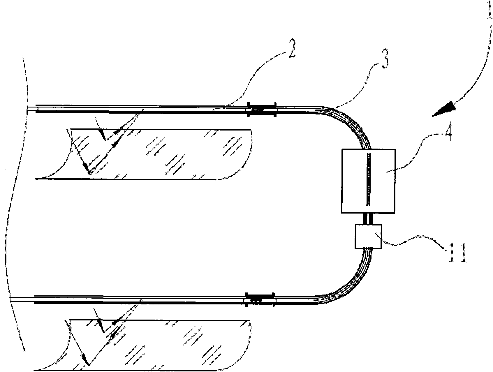
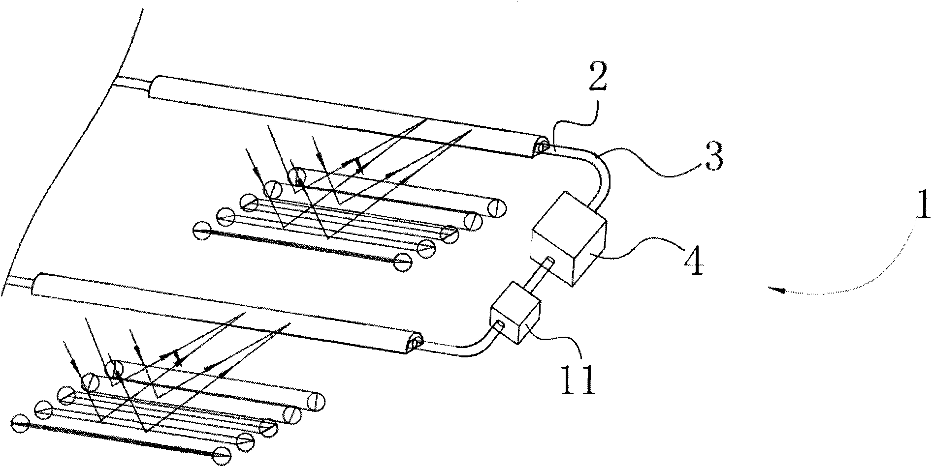
[0051] Figure 1a and Figure 1bIt is a schematic layout diagram of a solar heat transfer device 1 according to an embodiment of the present invention. The heat transfer device 1 includes a heat receiving area 2 , a turning area 3 and a heat releasing area 4 , where the positions corresponding to the heat receiving area 2 are respectively the telephoto line positions of the solar parabolic reflector trough or the Fresnel reflector array. The heated area 2 receives sunlight reflected from the reflector. The solar heat transfer device 1 has a ring structure as a whole, wherein the heat receiving area 2 is in the shape of a long straight line, and its length is, for example, at least 10 meters.

[0052] figure 2 It is a schematic diagram of the heat receiving area 2 in the heat transfer device 1 . The heated area 2 receives the long focal line position of the solar reflection trough, receives the energy from the sun, and its whole is linear. The heated zone 2 comprises an ou...


PUM


Abstract

The invention discloses a solar heat transfer unit (1). The solar heat transfer unit (1) comprises a heat-absorbing area (2), a heat-releasing area (4), a fixed-shape heat-transfer medium and a driving device (11), wherein the interiors of the heat-absorbing area (2) and the heat-releasing area (4) are provided with inner-layer metal tubes, and the fixed-shape heat-transfer medium penetrates through the inner-layer metal tubes; the heat-absorbing area (2) is arranged at the position capable of receiving solar energy rays, a coating with high absorption rate and low emittance is coated on the external surface of the part of the heat-absorbing area by the inner-layer metal tube; and the driving device (11) can drive the fixed-shape heat-transfer medium to run in the solar heat transfer unit (1). The invention has the following advantages: the unit can be subjected to mass production and installation in a large size; a sphere metal or sphere ceramic (5) of the fixed-shape heat-transfer medium has high coefficient of heat conductivity, thus the heat transfer efficiency is high, no leak danger exists and an environmentally-friendly goal can be realized; the unit has the ultra-high temperature heat-transfer capacity; the unit has low cost, stable performance and long service life and is easy to manufacture.

Description

technical field [0001] The present invention relates to a heat transfer device, in particular to a solar heat transfer device for a solar energy concentration device. Background technique [0002] As a kind of clean and environment-friendly energy, solar energy has been devoted to its development and utilization for a long time. Especially in recent years, due to the rising oil price, the improvement of environmental protection requirements, and the limitation of atmospheric carbon dioxide emissions, countries have worked harder to carry out research on solar energy utilization. A lot of work has been done on solar thermal utilization in China. Residential solar water heater technology is very mature, but water heaters belong to the category of low-temperature solar thermal utilization. At present, a small number of domestic researchers have started research on solar thermal utilization, using solar energy to obtain high temperature steam. In the research of solar thermal p...

Claims


Application Information

Patent Timeline
Patent Type & Authority Applications(China)
IPC IPC(8): F24J2/00F24J2/48F24J2/46
CPCY02E10/40
Inventor 刘阳
Owner BEIJING TERASOLAR PHOTOTHERMAL TECH CO LTD
Learn More