Bifocus micro lens with aspheric surface and adjustable focal length

An aspheric, bifocal technology, applied in the direction of lens, nonlinear optics, optics, etc., can solve the problems that it is difficult to realize the surface structure of aspheric microlens, the structure of microlens array, and the surface shape cannot be precisely controlled. Easy to design and process, easy to realize the array structure, easy to control the effect precisely

Inactive Publication Date: 2012-02-01
UNIV OF ELECTRONICS SCI & TECH OF CHINA
View PDF5 Cites 9 Cited by
  • Summary
  • Abstract
  • Description
  • Claims
  • Application Information

AI Technical Summary

Problems solved by technology

In 2005, H.W.Choi et al. reported a fabrication method of bifocal aspheric microlenses (see literature H.W.Choi, E.Gu, C.Liu, J.M.Girkin, and M.D.Dawson, Fabrication and evaluation of GaN negative and bifocal microlenses , Journal of Applied Physics, Vol.97, No.6, 2005: 063101(1-3)), but its focal length cannot be changed, which belongs to "static" optical components, that is, once the design and production of the lens are completed, the The optical properties and functions of the lens or the micro-optical system composed of the lens are completely determined and cannot be adjusted
However, this kind of bifocal microlens belongs to spherical microlens, its surface shape cannot be p

Method used


Image

  • Bifocus micro lens with aspheric surface and adjustable focal length
  • Bifocus micro lens with aspheric surface and adjustable focal length
  • Bifocus micro lens with aspheric surface and adjustable focal length

Examples


Embodiment Construction

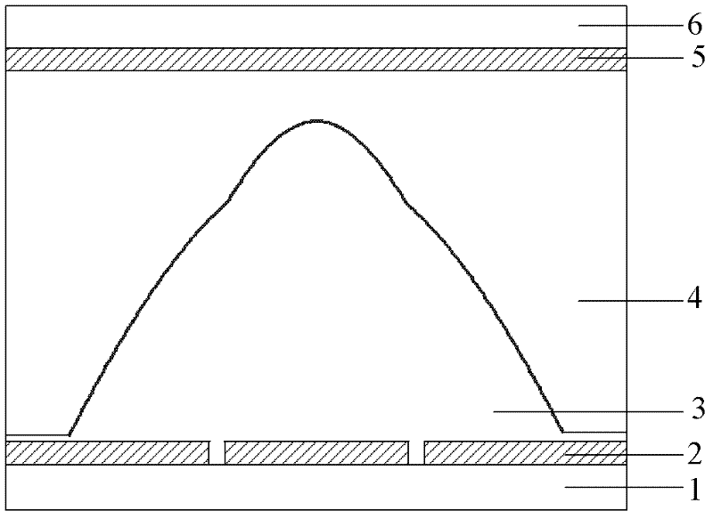
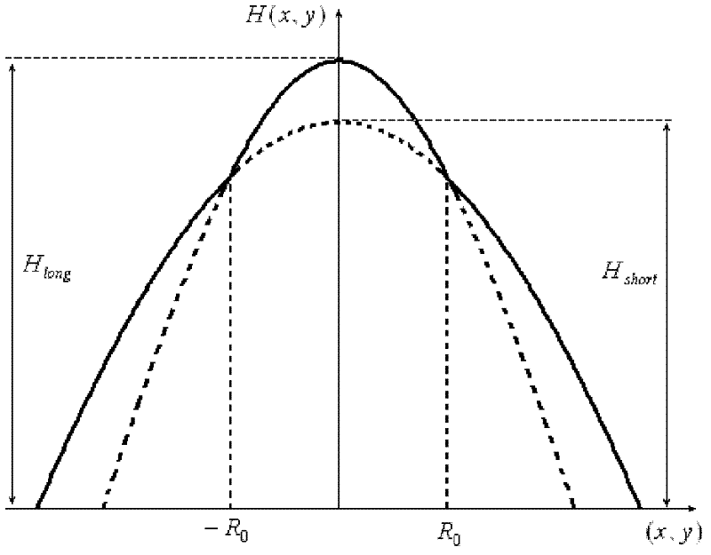
[0019] A bifocal aspheric microlens with adjustable focal length, such as figure 1 As shown, it includes a lower transparent glass substrate 1 , a lower ITO electrode 2 , a liquid crystal layer 3 , a liquid crystal sealing layer 4 , an upper ITO electrode 5 and an upper transparent glass substrate 6 . The upper ITO electrode 5 is located between the upper transparent glass substrate 6 and the liquid crystal sealing layer 4 , and the lower ITO electrode 2 is located between the lower transparent glass substrate 1 and the liquid crystal layer 3 . The surface of the liquid crystal sealing layer 4 in contact with the liquid crystal layer 3 is a concave aspheric shape, and the concave aspheric shape is as follows image 3As shown, it is formed by the intersection of rotationally symmetric surface 1 with higher height but smaller radius of curvature and rotationally symmetric surface 2 with lower height but larger radius of curvature. The material of the liquid crystal sealing laye...


PUM


Abstract

The invention discloses a bifocus micro lens with an aspheric surface and adjustable focal length, belonging to the technical field of optical devices. The bifocus micro lens with the aspheric surface and the adjustable focal length comprises an upper transparent glass substrate, a lower transparent glass substrate, an upper ITO (Indium Tin Oxide) electrode, a lower ITO electrode, a liquid crystal layer and a liquid crystal sealing layer; the contacting surface of the liquid crystal sealing layer and the liquid crystal layer is in a concave aspheric surface shape formed by intersecting a first rotational symmetroid with larger height and smaller curvature radius and a second rotational symmetroid with smaller height and larger curvature radius; the upper ITO electrode has the same shape with the bottom surface of the liquid crystal layer; and the lower ITO electrode consists of an inner circular electrode and an outer annular electrode which are insulated mutually. The bifocus micro lens with the aspheric surface and the adjustable focal length in the invention realizes focal length adjustment and bifocus independent control based on a photoelectric effect of a liquid crystal, has the advantages of compact structure, simple and convenient design and process, easiness in realizing an array structure and integrating with other optical devices, high control speed and the like, and has a wide application prospect in a micro optical system and a micro-optical-electro-mechanical system.

Description

technical field [0001] The invention belongs to the technical field of optical components, and relates to a bifocal aspheric microlens, in particular to a bifocal aspheric microlens with adjustable focal length. Background technique [0002] The design, manufacture and application of microlenses are one of the important contents of micro-optics research. Compared with bulk lenses, microlenses have the advantages of small size, light weight, and easy arraying and integration. And many other fields have been widely used, and the application field is constantly expanding, playing an irreplaceable role in traditional optical components. Microlenses are divided into spherical microlenses and aspheric microlenses according to their surface shapes. Spherical microlenses have the characteristics of relatively simple design and production, but the quality of imaging and focal spots deteriorates due to irreversible aberrations, which have a serious adverse effect on the performance ...

Claims


Application Information

Patent Timeline
IPC IPC(8): G02B3/02G02F1/137
Inventor 唐雄贵童伟廖进昆陆荣国李和平刘永刘永智
Owner UNIV OF ELECTRONICS SCI & TECH OF CHINA
Why Eureka
Try Eureka