This helps you quickly interpret patents by identifying the three key elements:
Problems solved by technology
Method used
Benefits of technology
Problems solved by technology
[0011] However, in Patent Document 1 and Patent Document 2, although the moment of inertia can be reduced by reducing the concave shape of the wall to improve responsiveness, in Patent Document 1, Figure 10 The concave-shaped front end portion 019 tends to cause stress concentration due to a sharp curvature change with a small radius of curvature. In addition, in Patent Document 2, Figure 11 The concave shape of the front end 028 is prone to stress concentration due to sharp curvature changes
[0012] Therefore, stress concentration tends to occur at the root of the rotor blade back surface of the hub member, and there are problems in terms of strength and durability.
Method used
Image
Click on the blue label to locate the original text in one second.
Reading with bidirectional positioning of images and text.
Examples
no. 1 approach
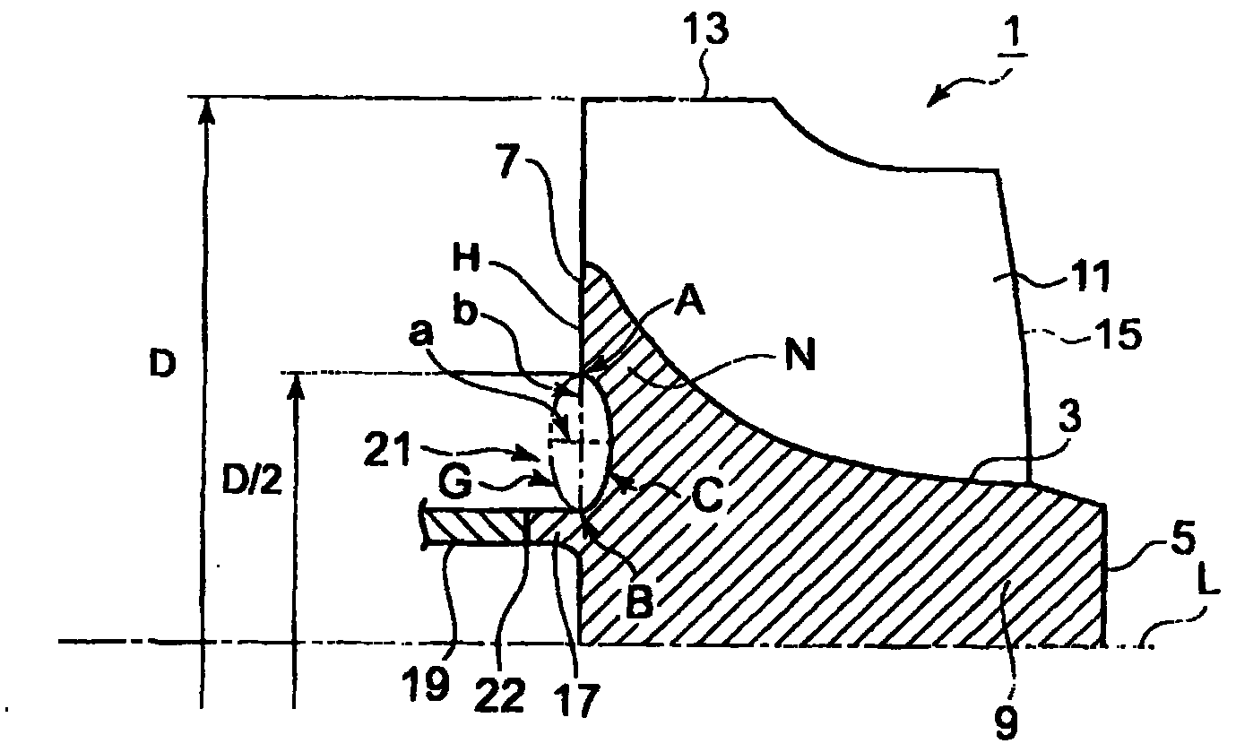
[0045] An example of an impeller motor wing for a turbocharger for a vehicle or a ship will be described. figure 1 Axial cross-sectional view of the impeller blade 1 is shown. In the impeller blade (hereinafter referred to as the blade) 1, a hub portion 9 formed in a shaft shape and having an outer peripheral side surface 3, a front end surface 5, a rear end surface (back surface) 7 and A plurality of wing portions 11 are integrally formed on the outer peripheral side surface 3 of the hub portion 9 by injection molding, casting, sintering, or the like.
[0046] The outer peripheral side surface 3 is curved so as to gradually increase in diameter from the front end surface 5 toward the rear surface 7 of the hub portion 9 , and a plurality of wing portions 11 are vertically provided on the curved surface along the axial direction.
[0047] Moreover, the leading edge 13 of the wing portion 11 is arranged on the outer peripheral side in the radial direction, and the trailing edge...
no. 2 approach
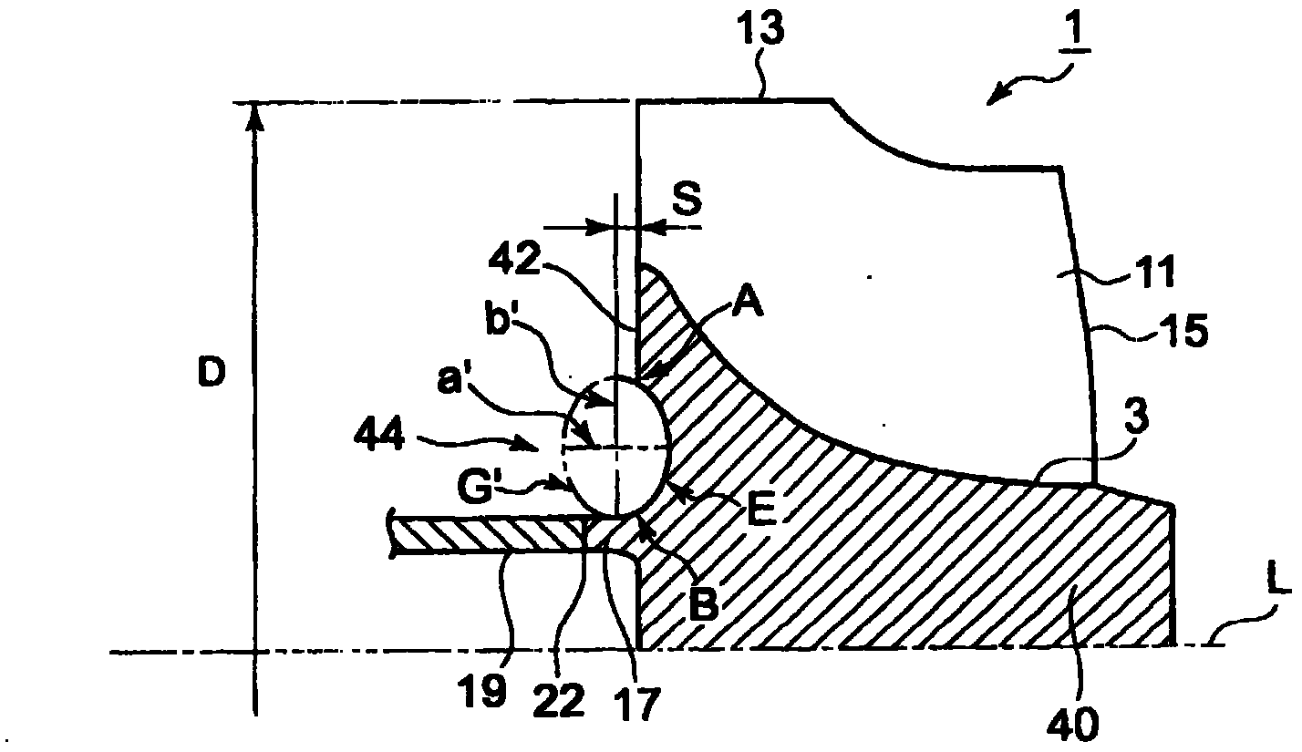
[0068] Next, refer to figure 2 A second embodiment will be described. In addition, the same code|symbol is attached|subjected to the same part as the structural member demonstrated in 1st Embodiment, and description is abbreviate|omitted.
[0069] Such as figure 2 As shown, on the back surface 42 of the hub portion 40, the cross-sectional shape of the annular concave portion 44 formed centering on the center line L of the rotating shaft 19 in the direction of the rotating shaft is composed of an ellipse G′, and the short diameter a′ The long arc E of the ellipse formed with the long diameter b' is formed. The major diameter b of the long arc E of this ellipse does not coincide with the back surface 42 . The major diameter b' is located at a position shifted by a distance s from the surface position of the back surface 42 toward the outer side of the hub portion 40, and is formed by a part of an elliptical long arc shape. That is, the curved shape forming the concave port...
no. 3 approach
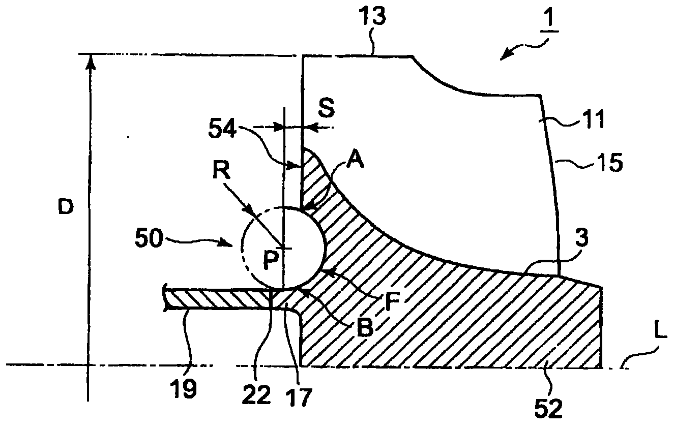
[0075] Next, refer to image 3 A third embodiment will be described. In addition, the same code|symbol is attached|subjected to the same member as the structural member demonstrated in 1st Embodiment and 2nd Embodiment, and description is abbreviate|omitted.
[0076] Compared with the ellipse of the second embodiment, the third embodiment forms the shape of the concave portion 50 by a circular arc.
[0077] Such as image 3As shown, on the back surface 54 of the hub portion 52 of the rotor blade 1, the cross-sectional shape of the annular concave portion 50 formed centering on the center line L of the rotating shaft 19 in the direction of the rotating shaft is constituted by an arc shape with a radius R. , formed by an arc F of a portion of the circumference. The center P of the arc F is located at a position displaced by a distance s from the surface position of the back surface 54 to the outside of the hub portion 52 as in the second embodiment. That is, the curved shape...
PUM
Abstract
Disclosed is a turbine rotor blade provided with the shape of the back surface of the rotor blade which while reducing the inertia moment of the rotor blade without changing the shapes of the blades, suppresses the occurrence of stress concentration at the root of the back surface of the rotor blade, thereby improving strength and durability. The turbine rotor blade (1) is obtained by integrally forming a shaft-shaped hub (9) connected with a rotary shaft (19) and the plurality of blades (11) formed in the periphery of the hub (9). The hub (9) has a shape gradually increasing in diameter toward the back surface (7) which is one end side thereof in the direction of the rotary shaft. In the back surface (7), an annular concave (21) is formed around the center line (L) of the rotary shaft (19). The cross-section shape of the concave (21) in the direction of the rotary shaft is formed of a long circular arc (C) of an ellipse obtained by dividing a curve shape symmetrical about the long axis such as an elliptical shape and an egg shape by the long axis, and formed such that the position of the long axis (b) matches with the back surface (7).
Description
technical field [0001] The present invention relates to a moving blade in a radial impeller such as a turbocharger, and a diagonal flow impeller, and particularly relates to the shape of the back surface of the moving blade. Background technique [0002] If the moment of inertia of the turbocharged airfoil of a turbocharger for a vehicle or a ship is large, as Figure 7 Responsiveness to an increase in the engine rotation speed and an increase in the air supply pressure are degraded, and as a result, a time lag occurs in the entire engine system including the turbocharger and the like. [0003] Therefore, as a method of reducing the moment of inertia of the turbo-turbine blade, a method of cutting off the shape of the blade itself and adjusting it is known. [0004] For example, it is known to reduce the Figure 8 The method of lowering the cover line 05 of the outer circumference of the wing 01 by the height of the trailing edge 03 of the wing 01 as shown, will Figure 9 ...
Claims
Application Information
Patent Timeline
Application Date:The date an application was filed.
Publication Date:The date a patent or application was officially published.
First Publication Date:The earliest publication date of a patent with the same application number.
Issue Date:Publication date of the patent grant document.
PCT Entry Date:The Entry date of PCT National Phase.
Estimated Expiry Date:The statutory expiry date of a patent right according to the Patent Law, and it is the longest term of protection that the patent right can achieve without the termination of the patent right due to other reasons(Term extension factor has been taken into account ).
Invalid Date:Actual expiry date is based on effective date or publication date of legal transaction data of invalid patent.
