Charge pump and phase locked loop using charge pump

A technology of charge pump and discharge current, which is applied in the field of phase-locked loop and charge pump, can solve problems such as charge pump paralysis, achieve the effects of reducing current spikes, realizing dynamic control, and high practical value

Active Publication Date: 2012-02-08
ZTE CORP +1
View PDF6 Cites 14 Cited by
  • Summary
  • Abstract
  • Description
  • Claims
  • Application Information

AI Technical Summary

Problems solved by technology

[0004] The technical problem to be solved by the present invention is to provide a phase-locked loop and a charge pump to solve the problem that the entire charge pump is paralyzed when the current matching circuit of the charge pump in the phase-locked loop fails, and to realize the current matching in the phase-locked loop. The charge pump can still work when the circuit fails

Method used


Image

  • Charge pump and phase locked loop using charge pump
  • Charge pump and phase locked loop using charge pump
  • Charge pump and phase locked loop using charge pump

Examples


Embodiment Construction

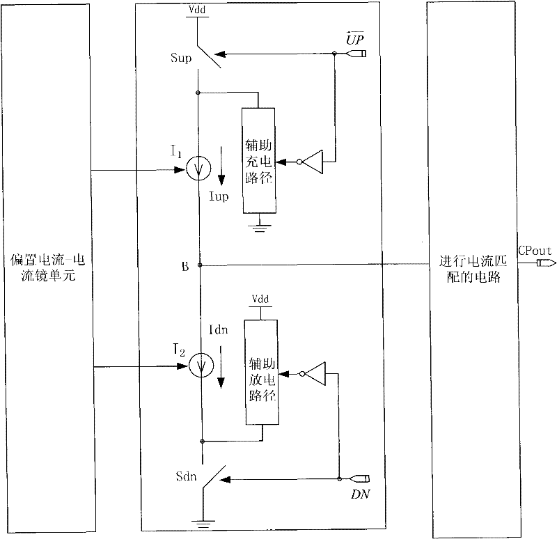
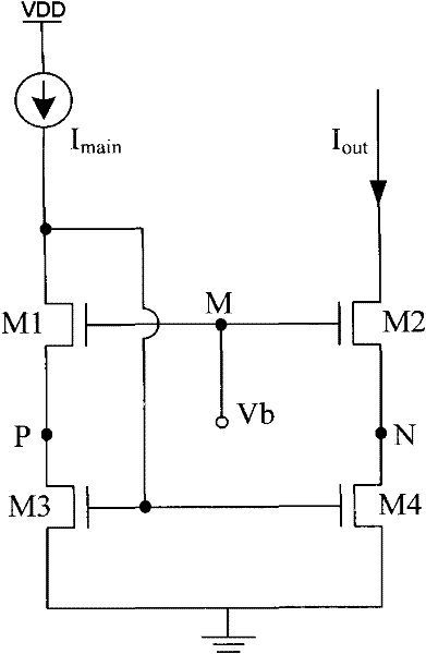
[0025] This embodiment is to improve the charge pump (CP) in the phase-locked loop (PLL) system, move the circuit for current matching out of the main circuit of the charge pump, set it up separately, and control the switch and the upper part of the main circuit of the charge pump Between the connection point of the current source and the lower control switch, between the connection point of the lower control switch and the lower current source and the upper control switch, an additional current path is connected in parallel, which can eliminate the current glitch phenomenon caused by charging and discharging; for charging and discharging To solve the problem of current mismatch, a compensating dynamic current matching circuit is designed.

[0026] The present embodiment will be described in detail below in conjunction with the accompanying drawings.

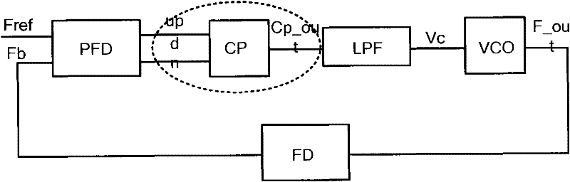
[0027] In the prior art, the charge pump includes a bias circuit-current mirror unit and the main circuit of the charge pump. ...


PUM


Abstract

The invention discloses a charge pump and a phase locked loop using the charge pump. The charge pump comprises a bias circuit-current mirror unit and a charge pump main circuit, wherein, the bias circuit-current mirror unit carries out biasing on a charging current source and a discharging current source from a bias current mirror image to the charge pump main circuit, the charge pump also comprises a circuit carrying out current coupling, the circuit is provided outside the charge pump main circuit, output terminal of the circuit is connected with an output terminal of the charge pump main circuit, and output current of the circuit carrying out current coupling is less than output current of the charge pump main circuit. According to an embodiment of the invention, through moving the circuit carrying out current coupling out of the charge pump main circuit, individual arrangement is employed, and when the circuit carrying out current coupling is broken, the charge pump still can work.

Description

technical field [0001] The invention relates to the technical field of integrated circuits, in particular to a charge pump and a phase-locked loop using the charge pump. Background technique [0002] Phase-locked loop (Phase Locked Loop, PLL) is a phase negative feedback control system, which can keep the frequency and phase of the controlled oscillator in a certain relationship with the input signal, and can suppress the noise in the input signal and the voltage-controlled oscillator. phase noise. Such as figure 1 As shown, the currently commonly used PLL is usually composed of a phase frequency detector (Phase Frequency Detector, PFD), a charge pump (Charge Pump, CP), a loop filter (Loop Filter, LPF), a voltage controlled oscillator (Voltage Control Oscillator, VCO) and frequency divider (Frequency Divider, FD) and other circuits composed of a system. [0003] The standard for measuring PLL performance is the size of the phase noise in the frequency domain, and the phas...

Claims


Application Information

Patent Timeline
Patent Type & Authority Applications(China)
IPC IPC(8): H03L7/08H03L7/113
Inventor 周滔
Owner ZTE CORP
Why Eureka
Try Eureka