
Sewage treatment artificial wetland system

An artificial wetland system and artificial wetland technology, applied in the field of sewage treatment wetland systems, can solve the problems of large demand for building materials, breeding of mosquitoes and flies, and construction investment of pipeline blockage, so as to improve water treatment efficiency, prevent fouling and blockage, and reduce The effect of land occupation

Active Publication Date: 2013-04-24
杨欣
View PDF5 Cites 1 Cited by
  • Summary
  • Abstract
  • Description
  • Claims
  • Application Information

AI Technical Summary

Problems solved by technology

[0004] 1) Constructed wetlands with surface flow type have stench and breeding of mosquitoes and flies, and the removal efficiency of pollutants is low;
[0005] 2) Horizontal subsurface flow constructed wetlands are composed of cover layer, filter material layer and anti-seepage layer, equipped with water inlet and outlet pipes, water inlet regulating valves and other devices, the structure is complex, pipeline blockage is prone to occur, and construction investment is high;
[0006] 3) Vertical flow artificial wetland is composed of covering layer, filter material layer, transition layer, drainage layer and anti-seepage layer. It needs a large number of perforated water distribution pipes while equipped with water inlet and outlet pipes and water inlet regulating valves. Vertical flow artificial wetland Wetland construction requires a large amount of construction, a large amount of building materials, and high construction costs;
[0007] 4) The above-mentioned wetlands can only accept the effluent that reaches or approaches the second-level water quality after the first-level pretreatment

Method used


Image

  • Sewage treatment artificial wetland system
  • Sewage treatment artificial wetland system
  • Sewage treatment artificial wetland system

Examples


Embodiment Construction

[0036] Preferred embodiments of the invention will be described in detail below.

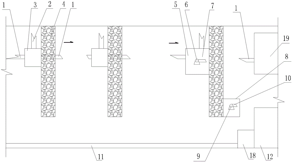
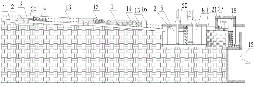
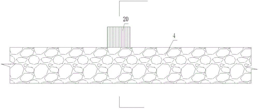
[0037] see figure 1 , figure 2 , Figure 7 The constructed wetland system for sewage treatment in this embodiment includes a main sewage pipe 1, a source sewage introduction pipe 2, an overflow diversion well 3, an underflow water distribution belt 4, a sewage sedimentation well 5, a sedimentation transfer pump 6, a sedimentation pump outlet pipe 7, two Level water quality storage well 8, water pump 9, water pump outlet pipe 10, interception guide ditch 11, first level water quality reservoir 12, shallow surface subsurface flow artificial wetland 13, intermittent overflow artificial wetland 14, seepage artificial wetland 15, water curtain Oxygen storm wall 16, primary treatment filter ditch 17, sand filter well water purification device 18 and biodigester 19, upward infiltration shut-off well 25 and siphon sewage discharge well 26.

[0038] see figure 1 , figure 2 , Figure 7, in order t...


PUM


Abstract

The invention relates to the technical field of sewage treatment, in particular to a sewage treatment artificial wetland system which has a simple structure and high pollutant removal efficiency. The system comprises an underflow water distribution belt, a shallow ground surface underflow artificial wetland and a first-stage pretreatment device, wherein a filter material is filled in the underflow water distribution belt; at least one part of the shallow ground surface underflow artificial wetland is covered by the underflow water distribution belt; the shallow ground surface underflow artificial wetland is a plant planting soil layer and is inclined downwards along a water flow direction; and the extension direction of the underflow water distribution belt is vertical to the water flow direction of the shallow ground surface underflow artificial wetland. By the sewage treatment artificial wetland system, sewage can be pretreated and precisely treated; and on the premise of small floor area, low construction input, low maintenance cost, high greening land utilization rates, high rain water closure rates and low energy consumption, the system can be widely applied to zero emission treatment of source sewage in an ecological cycle mode in mountain and plain regions, and the highest quality of treated water can reach a first (A)-level standard.

Description

technical field [0001] The invention relates to the technical field of sewage treatment, in particular to a sewage treatment wetland system. Background technique [0002] At present, constructed wetlands have been gradually applied to the advanced treatment of domestic sewage and industrial wastewater. The "Guidelines for Constructed Wetland Sewage Treatment Technology" (hereinafter referred to as : "Guidelines") put forward basic principles and requirements for the construction of constructed wetlands, and the present invention aims at the types of constructed wetlands proposed in "Guidelines" 1-2.1 and the third part of constructed wetlands under the premise of complying with these principles and requirements A new type of constructed wetland system for sewage treatment is designed based on the shortcomings and deficiencies of sewage treatment technology and examples. [0003] The shortcomings of the constructed wetland types and technologies proposed in the "Guidelines":...

Claims


Application Information

Patent Timeline
Patent Type & Authority Patents(China)
IPC IPC(8): C02F3/32C02F9/14
CPCY02W10/10
Inventor 杨欣
Owner 杨欣
Learn More