Manufacture method for polarization maintaining fiber and polarization maintaining fiber

A polarization-maintaining optical fiber and manufacturing method technology, which is applied to polarization optical fibers, cladding optical fibers, and manufacturing tools, etc., can solve the adverse effects of polarization-maintaining optical fibers on the strength and optical performance, the difficulty of satisfying the small force of the drill bit, and the roughness of the inner surface of the processing hole. Advanced problems, to achieve good optical performance and reliability, low attenuation, good symmetry

Inactive Publication Date: 2012-02-15
RUIGUANG TELECOMM TECH CO LTD
View PDF6 Cites 226 Cited by
  • Summary
  • Abstract
  • Description
  • Claims
  • Application Information

AI Technical Summary

Problems solved by technology

However, drilling requires high-precision mechanical finishing. Due to the relationship between precision, a slight deviation will result in high roughness of the inner surface of the processed hole and poor symmetry between the two processed holes; in addition, the requirements for the drill bit are high. Small force is not easy to satisfy. As the processing depth increases, the tip of the drill bit will swing outward by centrifugal force, the exit of the processing hole will be larger than the entrance of the processing hole, and the processing efficiency is low; in summary, it will affect all The strength and optical properties of the processed PM fiber are adversely affected

Method used


Image

  • Manufacture method for polarization maintaining fiber and polarization maintaining fiber
  • Manufacture method for polarization maintaining fiber and polarization maintaining fiber
  • Manufacture method for polarization maintaining fiber and polarization maintaining fiber

Examples


Embodiment 1

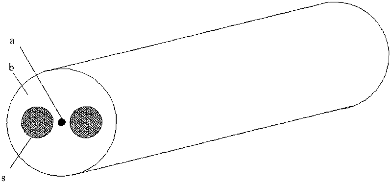
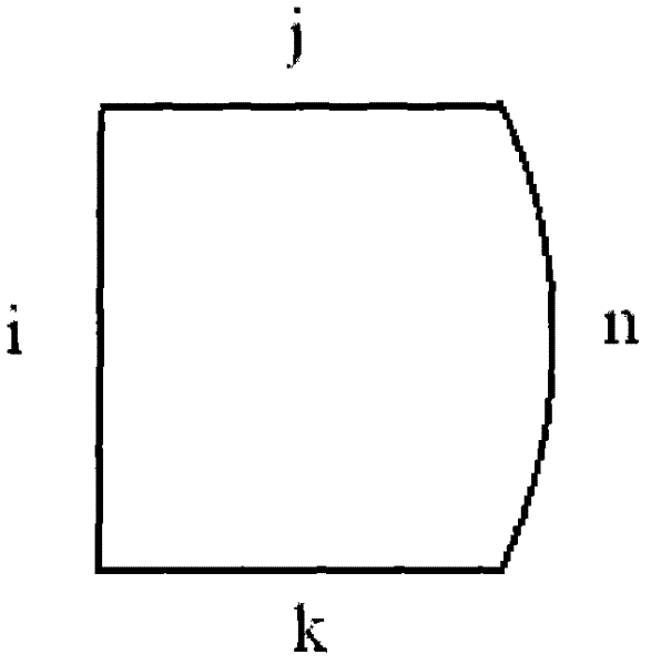
[0038] Such as Figure 2 to Figure 5 As shown, the glass mother bar e is processed into a cylinder, and its cross-section includes three right-angled sides i, j, k and an arc side n, wherein the right-angled sides j and k are parallel to each other, and the length is 15.10mm, and the right-angled side i is connected to one end of right-angled sides j and k respectively, and the length is 16.80mm. The arc side n is complementary to the side line of the cross-section of the glass mother rod e, and the radius of curvature of the arc side n is 21.60 mm. The core layer diameter is 3.79mm, the cladding diameter is 43.20mm quartz glass master rod e is processed from the side surface inwards two slots g opposite to each other and of the same shape, the size of the slot g matches the size of the stress rod s , the fit error is 0.12 mm, and the centerlines of the two slots g and the axis of the mother rod e are located on the same plane. As mentioned above, the center C2 of the cross-...

Embodiment 2

[0044] Such as Figure 2 to Figure 5 As shown, the glass mother rod e is processed into a cylinder, and its cross-section includes three right-angled sides i, j, k and one arc side n, wherein the right-angled sides j and k are parallel to each other, and the length is 17.62mm, and the right-angled side i is connected to one end of right-angled sides j and k respectively, and the length is 19.60mm. The arc side n is complementary to the side line of the cross-section of the glass mother rod e, and the radius of curvature of the arc side n is 25.20mm. The core layer diameter is 4.42mm, the cladding diameter is 50.40mm quartz glass mother rod e is machined from the side surface inwards two slots g which are oppositely arranged and have the same shape, and the size of the slot g matches the size of the stress rod s , the matching error is 0.15 mm, and the centerlines of the two slots g and the axis of the mother bar e are located on the same plane. As mentioned above, the center...

Embodiment 3

[0050] Such as Figure 2 to Figure 5 As shown, the glass mother bar e is processed into a cylinder, and its cross section includes three right-angled sides i, j, k and one arc side n, wherein the right-angled sides j and k are parallel to each other, and the length is 16.36mm, and the right-angled side i is connected to one end of right-angled sides j and k respectively, and the length is 18.20mm. The arc side n is complementary to the side line of the cross-section of the glass mother rod e, and the radius of curvature of the arc side n is 23.40 mm. The core layer diameter is 4.10mm, the cladding diameter is 46.80mm quartz glass master rod e is processed from the side surface inwards two slots g that are oppositely arranged and have the same shape, and the size of the slot g matches the size of the stress rod s , the fit error is 0.12 mm, and the centerlines of the two slots g and the axis of the mother rod e are located on the same plane. As mentioned above, the center C2 ...


PUM


Abstract

The invention provides a manufacture method for polarization maintaining fiber and a polarization maintaining fiber, and relates to optical waveguide fibers in the field of fiber-optical communication and fiber optical sensors. The method comprises the following steps that: (1) two oppositely arranged open slots with a same shape are inwardly provided at a side surface of a glass mother rod, stress rods are machined to obtain a shape matching the open slots, and the centers of the cross sections of the two open slots and the center of circle in the cross section of the glass mother rod are in a same line; (2) the stress rods are respectively inserted into each open slot on the glass mother rod, and the assembled glass mother rod and stress rods are put in a cannula to form a preformed rod of the polarization maintaining fiber; (3) the preformed rod of the polarization maintaining fiber is drew to form the polarization maintaining fiber. According to the invention, the glass mother rod is provided with the open slots, and the stress rods are embedded in the open slots, thereby obtaining high process repeatability; inner surfaces of the open slots have high fineness, and the open slots have good symmetry, thereby improving processing efficiency; therefore, the optical performance and reliability of the polarization maintaining fiber are substantially improved.

Description

technical field [0001] The invention relates to an optical waveguide fiber in the fields of optical fiber communication and optical fiber sensing, in particular to a method for manufacturing a polarization-maintaining optical fiber and the polarization-maintaining optical fiber. Background technique [0002] Transverse Spatial Mode HE for Standard Single-Mode Optical Fiber Transmission 11 , are actually two orthogonal modes HE 11 x and HE 11 y The degenerate mode of , in this mode the modal transmission constant βx≈βy. However, due to the fact that the actual single-mode fiber is not ideally circular in geometric size, as well as the influence of external stress, bending and torsion and other factors, the mode degeneracy is destroyed. The two modal transmission constants βx and βy are different, resulting in the mode State birefringence (geometric birefringence and stress birefringence), resulting in a phase difference between the orthogonal mode components and a delay ...

Claims


Application Information

Patent Timeline
Patent Type & Authority Applications(China)
IPC IPC(8): C03B37/027G02B6/024
CPCC03B37/01217C03B2203/31
Inventor 陈伟李诗愈柯一礼莫琦胡福明罗文勇黄文俊杜城
Owner RUIGUANG TELECOMM TECH CO LTD
Why Eureka
Try Eureka