Combined quenching tank provided with inner tank with bottom inserted propeller
A propeller and combined technology, applied in quenching devices, heat treatment equipment, manufacturing tools, etc., can solve the problems of difficult equipment installation, maintenance and cleaning, insufficient cooling capacity, low stirring efficiency, etc., to achieve reduced power, low power consumption, Effect of improving flow uniformity
- Summary
- Abstract
- Description
- Claims
- Application Information
AI Technical Summary
Problems solved by technology
Method used
Image
Examples
Embodiment 1
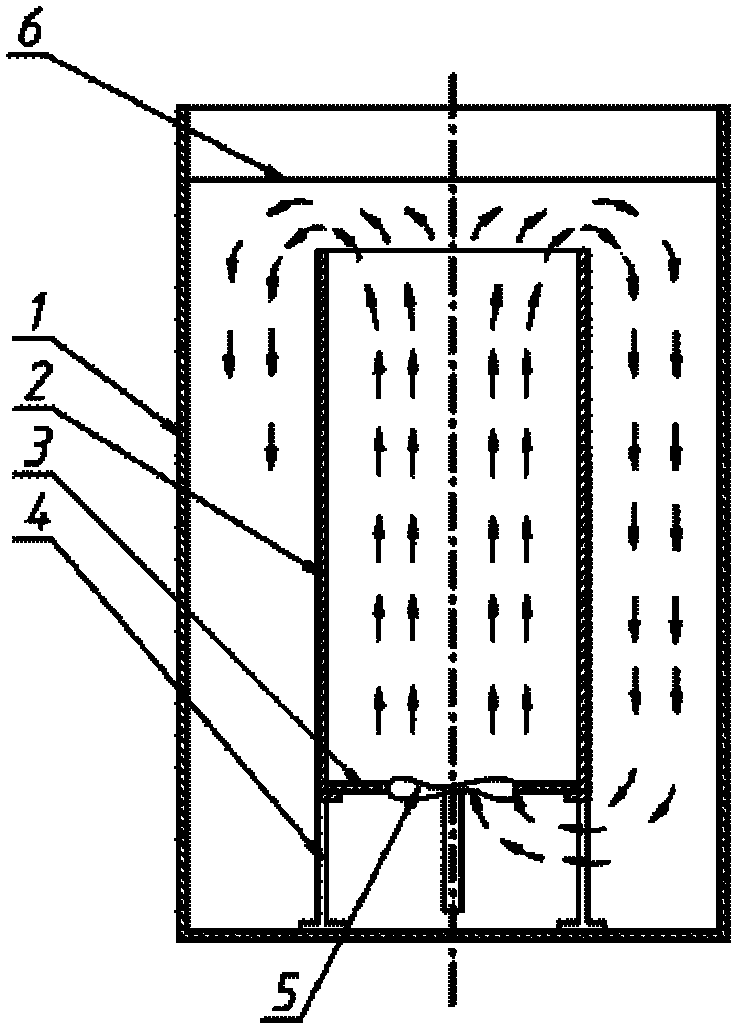
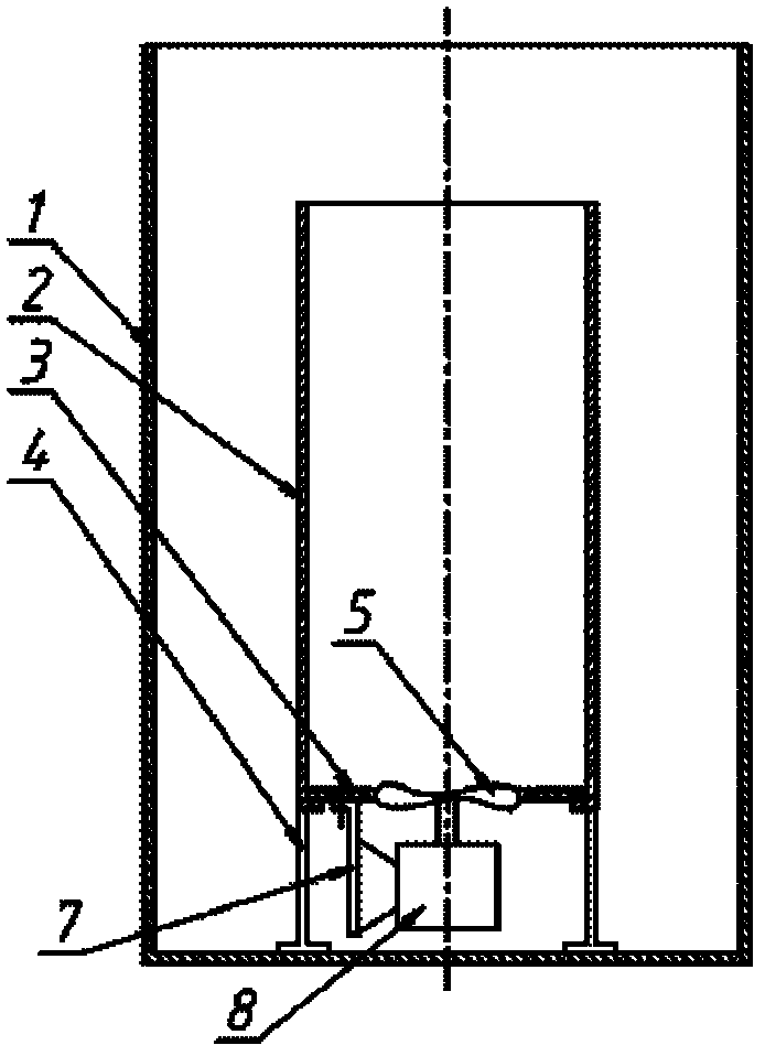
[0049] Such as figure 1 As shown, this embodiment includes: an outer tank 1, an inner tank cylinder 2, a bottom plate 3, a bracket 4, and a bottom-inserted stirring propeller 5, wherein:
[0050] The bracket 4 is located at the bottom of the outer tank 1, the inner tank cylinder 2 is located on the bracket 4, the height of the upper opening of the inner tank 2 is lower than the liquid level 6, the height of the liquid level is lower than the upper opening of the outer tank, and the bottom plate 3 is located on the inner tank cylinder 2, the bottom inserts the stirring propeller 5 and is arranged in the water inlet on the bottom plate 3. Driven by the stirring propeller, the liquid at the bottom of the outer tank is transported to the inner tank, so that the liquid moves from bottom to top in the inner tank, and overflows from the upper mouth of the inner tank to the gap between the outer tank and the inner tank. And flow back down to the bottom of the outer tank.
[0051] W...
Embodiment 2
[0058] Embodiment 2 Bottom inserted propeller type combined quenching tank
[0059] Quenching tank volume 1000m 3 , the structure of the quenching tank is as follows Figure 11 shown. The diameter of the outer tank is Φ12m and the height is 10m. The diameter of the inner tank is Φ9.5m and the height is 7.5m. The inner tank is located on the bracket, and the bracket is placed on the bottom of the outer tank. There are 31 holes of Φ800 on the bottom plate, and a stirring propeller with a diameter of Φ660 is installed in each hole, a total of 31 propellers. They are respectively driven by 31 15Kw submersible sealed motors. According to each propeller agitator provides 3300m 3 / h flow calculation, the average flow velocity in the inner tank can reach 0.45m / s. The total power of the driving motor is 465Kw. The upper part of the outer tank has an overflow tank with a diameter of 13.6m. The overflow pipeline leads to the external storage tank and passes through 4 sets of 4000m ...
Embodiment 3
[0060] Embodiment 3 Bottom inserted propeller combined quenching tank
[0061] The size of the outer tank is 7×7×8H meters. Equipped with two sets of replaceable inner tanks, one of which, such as Figure 9 So, it is shown as a Φ5.5×5m, and there are 6 bottom water inlet holes of Φ800 on the bottom plate. Each hole is equipped with a Φ660 spiral agitator driven by a 15Kw submersible sealed motor with a total power of 105Kw. The flow rate of each propeller is 3300m 3 / h. The flow velocity in the cross section of the inner tank is about 0.27m / s. Another set of inner tanks is 4 independent inner tanks such as Figure 10 As shown, each inner tank has a diameter of Φ2.5m and a height of 5m. There is a Φ600 bottom water inlet hole on each bottom plate, and a Φ508 stirring propeller is installed in the hole, with a flow rate of 1100m 3 / h. The propeller is driven by an overhead vertical motor with a power of 5.25Kw. The motor seat of the vertical motor is set on the top of e...
PUM
 Abstract
Description
Claims
Application Information
 - R&D
- Intellectual Property
- Life Sciences
- Materials
- Tech Scout
- Unparalleled Data Quality
- Higher Quality Content
- 60% Fewer Hallucinations
Browse by: Latest US Patents, China's latest patents, Technical Efficacy Thesaurus, Application Domain, Technology Topic, Popular Technical Reports.
© 2025 PatSnap. All rights reserved.Legal|Privacy policy|Modern Slavery Act Transparency Statement|Sitemap|About US| Contact US: help@patsnap.com


