Olefin polymerization reactor

A technology of olefin polymerization and reactor, which is applied in the field of reactors, can solve the problems of the research on the unseen variable-diameter kettle and the expansion section, etc., and achieve the effects of improving heat removal capacity, small stirring power, and reducing operating costs

Inactive Publication Date: 2013-03-20
CHINA PETROLEUM & CHEM CORP +1
View PDF8 Cites 0 Cited by
  • Summary
  • Abstract
  • Description
  • Claims
  • Application Information

AI Technical Summary

Problems solved by technology

The above patents are all aimed at the liquid-solid two-phase loop reactor, but for the slurry entrainment problem of the widely used gas-liquid-solid three-phase slurry stirred tank reactor, there is no research on the variable diameter tank and the expansion section.

Method used


Image

  • Olefin polymerization reactor
  • Olefin polymerization reactor
  • Olefin polymerization reactor

Examples


Embodiment 1

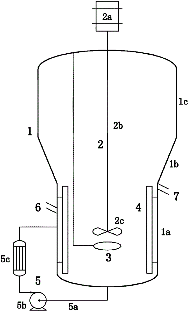
[0047] As attached figure 1 As shown, an olefin polymerization reactor includes:

[0048] The polymerizer body 1 is composed of a reaction section 1a, an expansion section 1c, and a connecting section 1b located between the reaction section 1a and the expansion section 1c;

[0049] The stirring device 2 installed in the center of the polymerization kettle body 1 to realize the three-phase mixing of gas, liquid and solid in the kettle, the stirring device 2 is composed of a transmission device 2a, a stirring shaft 2b and a stirring turbine 2c connected in sequence;

[0050] A gas distribution device 3 for dispersing the raw material gas flowing into the reactor is located in the reactor body 1 of the polymerization reactor;

[0051] A baffle 4 located near the inner wall surface of the reaction section 1a of the polymerization tank for enhancing the mixing effect in the tank;

[0052] The slurry external circulation system 5 for the external circulation and heat removal of the slurry is ...

Embodiment 2

[0065] A cold mold device was established in the laboratory, and the cold mold experiment of gas-liquid-solid three-phase slurry entrainment was performed in four stirred tanks with different enlarged section diameters.

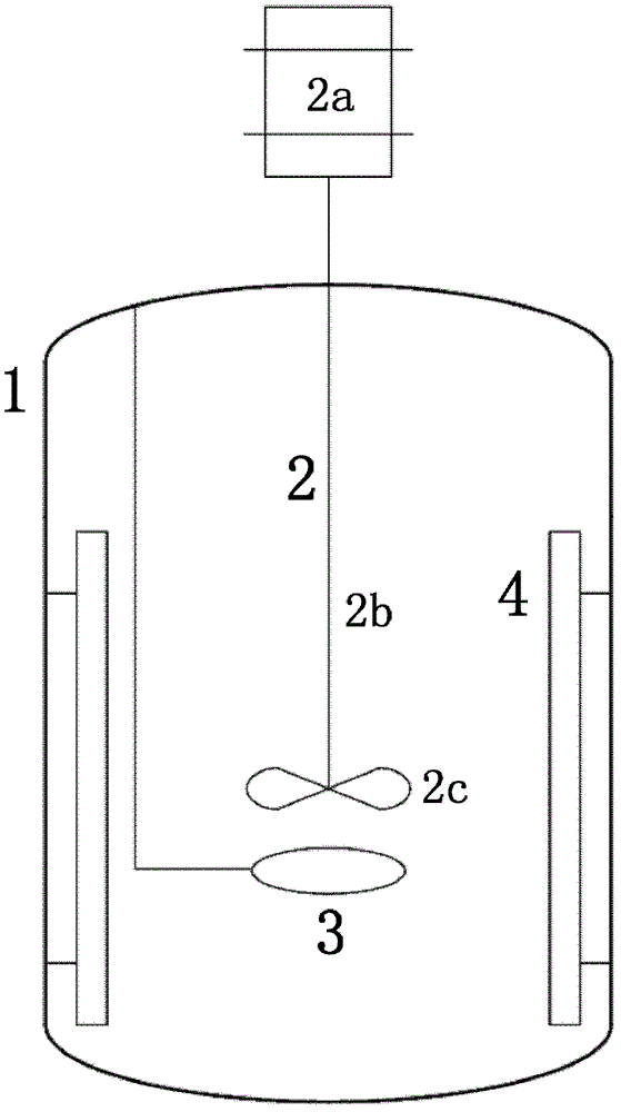
[0066] The 1# stirred tank is an ordinary stirred tank without expansion section and connecting section, and its structure is as attached figure 2 As shown, it includes: a vertical cylindrical polymerizer body 1, which is installed in the center of the polymerizer body 1 to achieve a three-phase mixing of gas, liquid and solid in the reactor, with a stirring device 2 which consists of a transmission device connected in sequence 2a. The stirring shaft 2b and the stirring turbine 2c are composed of; a gas distribution device 3 located in the polymerization vessel body 1 for dispersing the raw material gas passing into the vessel; and located near the inner wall surface of the lower middle and lower part of the polymerization vessel body 1 for strengthening the vess...

Embodiment 3

[0088] A cold mold device was established in the laboratory, and the cold mold experiment of gas-liquid-solid three-phase slurry entrainment was carried out in two stirred tanks with different expansion sections.

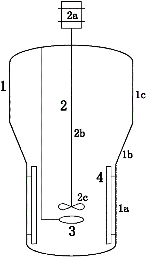
[0089] The 3# stirred tank is the 3# stirred tank in Example 1. The vertical cylindrical enlarged section 1c and the inverted cone connecting section 1b are used. The inner diameter of the enlarged section 1c is 1.73 times the inner diameter of the reaction section 1a; 5# Stirring kettle as attached Figure 4 As shown, except that the spherical top expansion section 1c (a kind of curved cylinder) is used, the diameter of the spherical part is the same as the inner diameter of the expansion section 1c of the 3# stirred tank, and the expansion section 1c is tangent to the connecting section 1b. 3# Stirring tank is the same. The inner diameter and height of the reaction section 1a and the inclination angle of the connecting section 1b are completely the same. The detaile...


PUM

PropertyMeasurementUnit
angleaaaaaaaaaa
densityaaaaaaaaaa

Abstract

The invention discloses an olefin polymerization reactor. The reactor comprises a polymerization kettle body, a stirring device, a feeding port and an overflowing port, wherein the polymerization kettle body is composed of a reaction segment, an enlargement segment, and a connection segment located between the reaction segment and the enlargement segment; the stirring device is arranged at the center inside the polymerization kettle body, is used for stirring raw materials in the kettle, and is composed of a transmission device, a stirring shaft and a stirring turbine which are sequentially connected; the feeding port is arranged on the side wall of the reaction segment of the polymerization kettle body and is used for adding solvent, catalyst and the like; and the overflowing port is used for discharging the slurry and controlling the liquid level in the kettle. By using the reactor, the entrainment can be effectively reduced.

Description

Technical field [0001] The invention relates to the field of reactors, in particular to an olefin polymerization reactor for olefin slurry polymerization. Background technique [0002] Polyolefin is an important branch of synthetic resin and the most important product in the modern petrochemical industry. The process of olefin polymerization mainly includes slurry method, gas phase method, solution method and so on. [0003] The slurry method has been widely used due to its early industrialization time, mature process technology and better product quality. The most representative slurry-method ethylene polymerization process is the stirred tank low-pressure slurry process of Mitsui Petrochemical Corporation for producing high-density and medium-density polyethylene (abbreviated as CX process). This process controls the molecular weight, molecular weight distribution and density of the product by changing the arrangement of the two polymerization vessels (parallel or series), chan...

Claims


Application Information

Patent Timeline
Patent Type & Authority Patents(China)
IPC IPC(8): C08F10/00C08F2/01
Inventor 阳永荣王靖岱黄正梁胡雨晨蒋斌波吴德荣王江义张斌李勇殷大斌贾中明朱宇飞张擎何乐路蒋云涛
Owner CHINA PETROLEUM & CHEM CORP
Why Eureka
Try Eureka