Combined quenching tank provided with inner tank with bottom inserted propeller

A propeller and quenching tank technology, applied in quenching devices, heat treatment equipment, manufacturing tools, etc., can solve problems such as equipment installation, maintenance and cleaning difficulties, insufficient cooling capacity, uneven flow field, etc., to achieve reduced power and low power consumption , The effect of small flow resistance

Active Publication Date: 2013-11-06
SHANGHAI JIAOTONG UNIV
View PDF6 Cites 0 Cited by
  • Summary
  • Abstract
  • Description
  • Claims
  • Application Information

AI Technical Summary

Problems solved by technology

[0015] The present invention aims at the above-mentioned deficiencies in the prior art, and provides a combined quenching tank with a propeller inner groove inserted at the bottom, which solves the problems of low stirring efficiency, uneven flow field, insufficient cooling capacity, equipment installation, Difficulty in maintenance and cleaning

Method used


Image

  • Combined quenching tank provided with inner tank with bottom inserted propeller
  • Combined quenching tank provided with inner tank with bottom inserted propeller
  • Combined quenching tank provided with inner tank with bottom inserted propeller

Examples


Embodiment 1

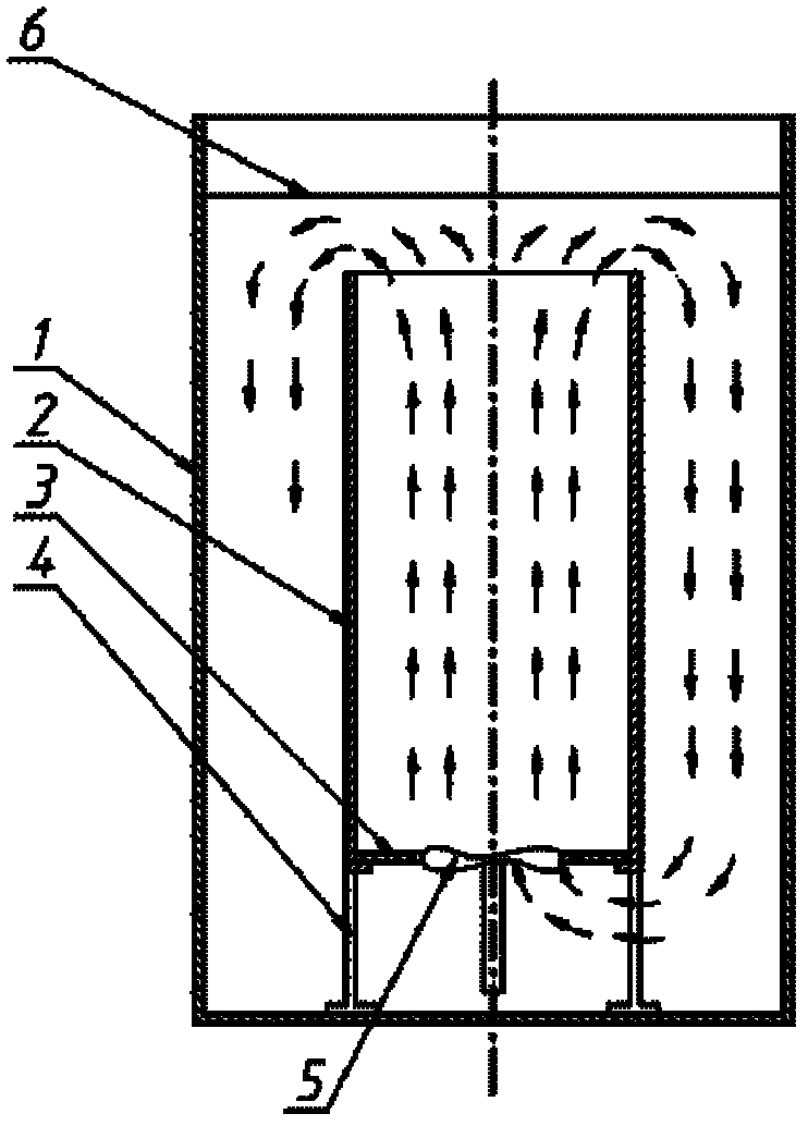
[0049] Such as figure 1 As shown, this embodiment includes: an outer tank 1, an inner tank cylinder 2, a bottom plate 3, a bracket 4, and a bottom-inserted stirring propeller 5, wherein:

[0050] The bracket 4 is located at the bottom of the outer tank 1, the inner tank cylinder 2 is located on the bracket 4, the height of the upper opening of the inner tank 2 is lower than the liquid level 6, the height of the liquid level is lower than the upper opening of the outer tank, and the bottom plate 3 is located on the inner tank cylinder 2, the bottom inserts the stirring propeller 5 and is arranged in the water inlet on the bottom plate 3. Driven by the stirring propeller, the liquid at the bottom of the outer tank is transported to the inner tank, so that the liquid moves from bottom to top in the inner tank, and overflows from the upper mouth of the inner tank to the gap between the outer tank and the inner tank. And flow back down to the bottom of the outer tank.

[0051] W...

Embodiment 2

[0058] Embodiment 2 Bottom inserted propeller type combined quenching tank

[0059] Quenching tank volume 1000m 3 , the structure of the quenching tank is as follows Figure 11 shown. The diameter of the outer tank is Φ12m and the height is 10m. The diameter of the inner tank is Φ9.5m and the height is 7.5m. The inner tank is located on the bracket, and the bracket is placed on the bottom of the outer tank. There are 31 holes of Φ800 on the bottom plate, and a stirring propeller with a diameter of Φ660 is installed in each hole, a total of 31 propellers. They are respectively driven by 31 15Kw submersible sealed motors. According to each propeller agitator provides 3300m 3 / h flow calculation, the average flow velocity in the inner tank can reach 0.45m / s. The total power of the drive motor is 465Kw. The upper part of the outer tank has an overflow tank with a diameter of 13.6m. The overflow pipeline leads to the external storage tank and passes through 4 sets of 4000m 3...

Embodiment 3

[0060] Embodiment 3 Bottom inserted propeller combined quenching tank

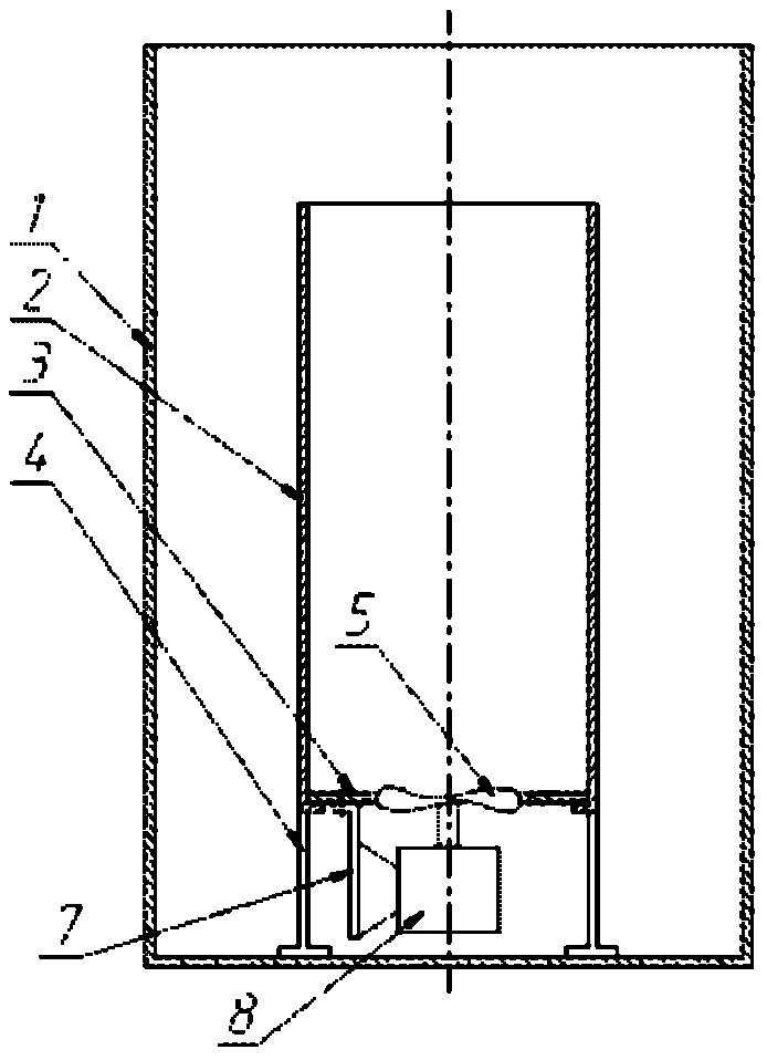
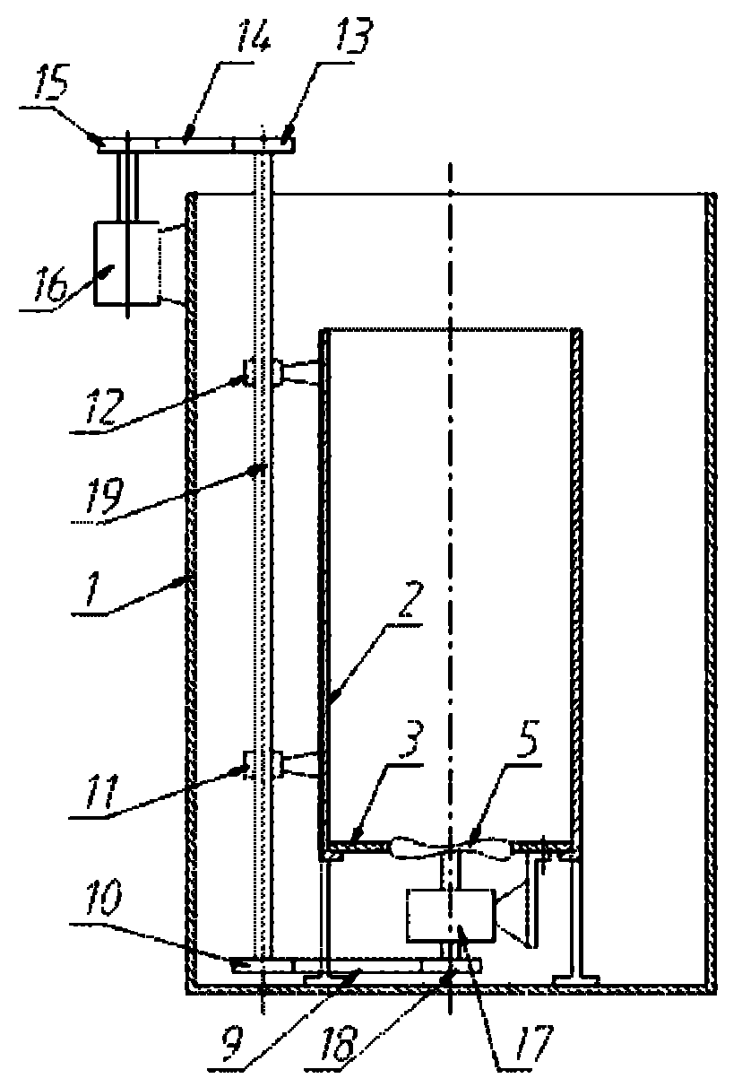
[0061] The size of the outer tank is 7×7×8H meters. Equipped with two sets of replaceable inner tanks, one of which, such as Figure 9 So, it is shown as a Φ5.5×5m, and there are 6 bottom water inlet holes of Φ800 on the bottom plate. Each hole is equipped with a Φ660 spiral agitator driven by a 15Kw submersible sealed motor with a total power of 105Kw. The flow rate of each propeller is 3300m 3 / h. The flow velocity in the cross section of the inner tank is about 0.27m / s. Another set of inner tanks is 4 independent inner tanks such as Figure 10 As shown, each inner tank has a diameter of Φ2.5m and a height of 5m. There is a Φ600 bottom water inlet hole on each bottom plate, and a Φ508 stirring propeller is installed in the hole, with a flow rate of 1100m 3 / h. The propeller is driven by an overhead vertical motor with a power of 5.25Kw. The motor seat of the vertical motor is set on the top of e...


PUM


Abstract

The invention discloses a combined quenching tank provided with an inner tank with a bottom inserted propeller, and belongs to the technical field of metal material heat treatment. The combined quenching tank comprises an outer tank, a support, at least one inner tank and corresponding bottom plate, and at least one stirring mechanism, wherein the outer tank and the inner tank form a structure which can be separated or combined relatively, the inner tank, the bottom plate and the support are arranged in the outer tank from top to bottom, the stirring mechanism is arranged in a corresponding water inlet on the bottom plate, the liquid at the bottom of the outer tank is delivered into the inner tank under the drive of the stirring mechanism, and the liquid moves in the inner tank from bottom to top, overflows from an upper opening of the inner tank to a gap between the outer tank and the inner tank and flows down and back to the bottom of the outer tank. By adopting the combined quenching tank provided with the inner tank with the bottom inserted propeller, higher stirring capability, uniform and oriented flow field and good cooling capability can be obtained. Meanwhile, the combined quenching tank structure can be combined flexibly according to the size of the workpiece and can also facilitate the installation, repair and cleaning of the equipment.

Description

technical field [0001] The invention relates to a device in the technical field of metal material heat treatment, in particular to a combined quenching tank with a bottom inserted propeller inner tank. Background technique [0002] Quenching is a common heat treatment process for rapidly cooling a heated workpiece. Quenching the workpiece by immersing it in a liquid medium such as water, aqueous solution, oil or molten salt is called immersion quenching. The cooling equipment used for immersion quenching is called quenching tank, for example, quenching water tank, quenching oil tank. Usually, a stirring device is set in the quenching tank. Stirring can improve the ability of the quenching medium to remove heat from the surface of the workpiece and the uniformity of cooling. Since the flow rate of the propeller agitator can be about 10 times larger than that of the pump with the same power, the propeller agitator device is widely used in the quenching tank. Early quenchin...

Claims


Application Information

Patent Timeline
Patent Type & Authority Patents(China)
IPC IPC(8): C21D1/63
Inventor 潘健生张幸骆晓萌顾剑锋韩利战
Owner SHANGHAI JIAOTONG UNIV
Why Eureka
Try Eureka