Wool filtering machine for water processing facility

A technology of water treatment and facilities, applied in the field of wool filter, can solve the problems of complex overall structure, large power consumption, and blockage of filter porous slots, etc., and achieve the effect of simple overall structure and convenient maintenance

Inactive Publication Date: 2012-02-22
常熟协顺纺织制衣有限公司
View PDF3 Cites 7 Cited by
  • Summary
  • Abstract
  • Description
  • Claims
  • Application Information

AI Technical Summary

Problems solved by technology

[0006] The above-mentioned patent scheme has the following shortcomings: the first is that the process wastewater mixed with hairy fibers will easily cause the pores of the filter porous groove to be blocked, and perhaps the patent scheme has realized this point, So a nylon brush is set on the edge of the spiral blade, and the wool fiber attached to the filter porous groove is removed by the nylon brush. The combination effect; the second is that the treatment efficiency is low, because a large amount of water will be driven out at the same time as the wool fiber is driven out from the hair outlet; the third is not conducive to saving energy, for example, the patented scheme must be equipped with a screw shaft for driving The rotating power transmission mechanism (the patent is called the motor) must be equipped with a water diversion mechanism (the patent is called the water pump) to draw out the water after the wool fiber is removed, and the use of two sets of power will cause a large power consumption; That is to say, during the whole process of the wool filter machine being in operation, it needs to be supervised by workers on site; fifth, the overall structure is complex and the operating cost is high

Method used


Image

  • Wool filtering machine for water processing facility
  • Wool filtering machine for water processing facility
  • Wool filtering machine for water processing facility

Examples


Embodiment Construction

[0023] In order to enable the examiners of the patent office, especially the public, to understand the technical essence and beneficial effects of the present invention more clearly, the applicant will describe in detail the following in the form of examples, but none of the descriptions to the examples is an explanation of the solutions of the present invention. Any equivalent transformation made according to the concept of the present invention which is merely formal but not substantive shall be regarded as the scope of the technical solution of the present invention.

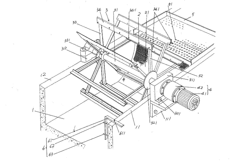
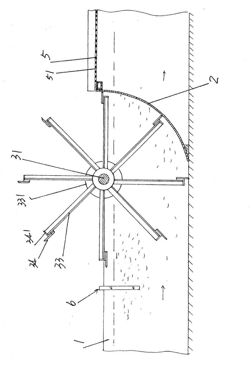
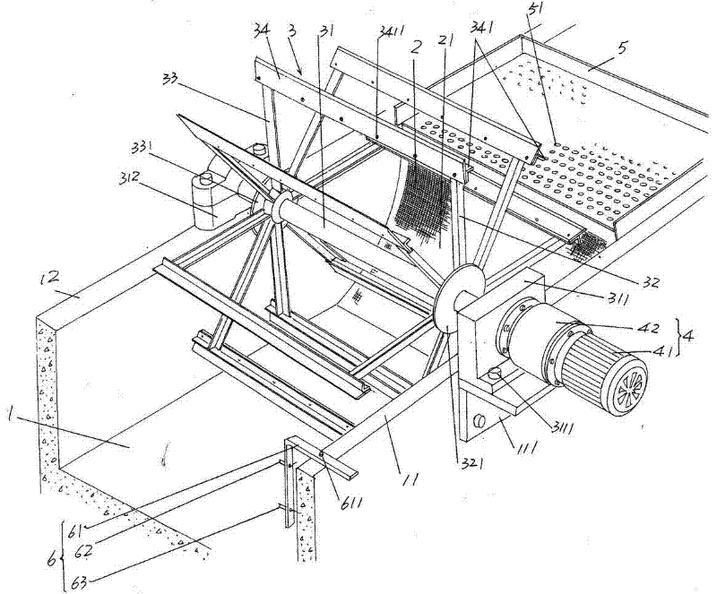
[0024] please see figure 1 and figure 2 , a water collection and diversion tank 1 of the water treatment facility is given. Taking the water treatment facility applied in the wool textile factory as an example, the water collection and diversion tank 1 is used to collect the water from loose wool dyeing, shrinking and washing, etc. Wastewater containing wool fibers (such as wool fibres) from productio...


PUM


Abstract

A wool filtering machine for a water processing facility belongs to the technical field of environmental facility. The water processing facility comprises a water collecting and guiding gutter with a first wall body and a second wall body. The wool filtering machine comprises the following components: a web plate arranged on a channel, which waste water passes through, of the water collecting and guiding gutter; a water-sprinkling and wool scraping dolly supported on the water collecting and guiding gutter and corresponding to a side of the web plate; a power transmission mechanism electrically connected with an electric control box, arranged on an outer wall on one side of the water collecting and guiding gutter and drivingly connected with the water-sprinkling and wool scraping dolly; a wool collecting and draining disc used for receiving wool fibres scraped from the web plate by the water-sprinkling and wool scraping dolly and draining off water adhesive to the wool fibres, and arranged on the water collecting and guiding gutter and on the other side of the web plate. The wool filtering machine of the invention has advantages of ideal wool fibre removal efficiency and effect, no special labor required, simple structure and convenient maintenance.

Description

technical field [0001] The invention belongs to the technical field of environmental protection facilities, and in particular relates to a wool filter machine for water treatment facilities, which is used for filtering wool fibers discharged from the production process of wool spinning industry and leather industry and mixed in sewage. Background technique [0002] As we all know, not limited to the above-mentioned wool spinning industry and fur or leather products industry, both need to treat the process water discharged during the production process, so as to protect the environment. Furthermore, as people know, during the production process of wool textile products, for example, waste water mixed with wool fibers will be discharged in processes such as loose wool dyeing process, shrinking machine shrinking process, and wool washing process. Similarly, in the production process of leather products, for example, in the depilation process of fur, wastewater containing hair w...

Claims


Application Information

Patent Timeline
Patent Type & Authority Applications(China)
IPC IPC(8): B01D33/15B01D33/46
Inventor 龚锦丰
Owner 常熟协顺纺织制衣有限公司
Why Eureka
Try Eureka