
Indexing and clamping device for numerically-controlled large spiral bevel gear broaching machine

A technology of spiral bevel gears and clamping devices, which is applied in gear tooth manufacturing devices, gear cutting machines, belts/chains/gears, etc., which can solve the problems of frequent indexing movements of indexing mechanisms, reduced indexing accuracy, and short time required and other problems to achieve the effect of realizing processing, eliminating the movement gap, and stabilizing the indexing process

Inactive Publication Date: 2012-02-22
TIANJIN NO 1 MACHINE TOOL WORKS
View PDF8 Cites 3 Cited by
  • Summary
  • Abstract
  • Description
  • Claims
  • Application Information

AI Technical Summary

Problems solved by technology

In the gear broaching machine in the prior art, during the workpiece cutting process, due to the frequent indexing action of the indexing mechanism, the required time is relatively short. When the worm gear meshes, the gap is difficult to quickly eliminate; Under the protection of no anti-backlash device, it will definitely affect and reduce its indexing accuracy
The workpiece clamping is to tighten the whole workpiece box through the hydraulic cylinder. Since the main cutting tool is concentrated on the workpiece box, the use of hydraulic clamping workpiece box cannot avoid the slight movement of the workpiece during the cutting process.
With the development of the automobile industry from large batches and few varieties to small and medium batches and many varieties, the demand for large and high-precision gears is increasing, and the quality requirements are also getting higher and higher. The traditional CNC spiral bevel gear pull The gear machine has been unable to meet the above requirements

Method used


Image

  • Indexing and clamping device for numerically-controlled large spiral bevel gear broaching machine
  • Indexing and clamping device for numerically-controlled large spiral bevel gear broaching machine

Examples


Embodiment Construction

[0012] In order to further understand the invention content, characteristics and effects of the present invention, the following examples are given, and detailed descriptions are as follows in conjunction with the accompanying drawings:

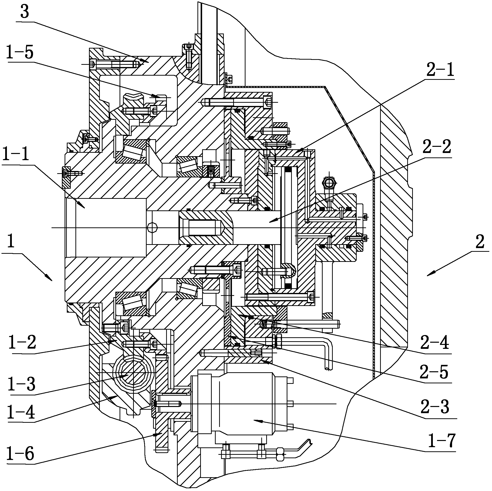
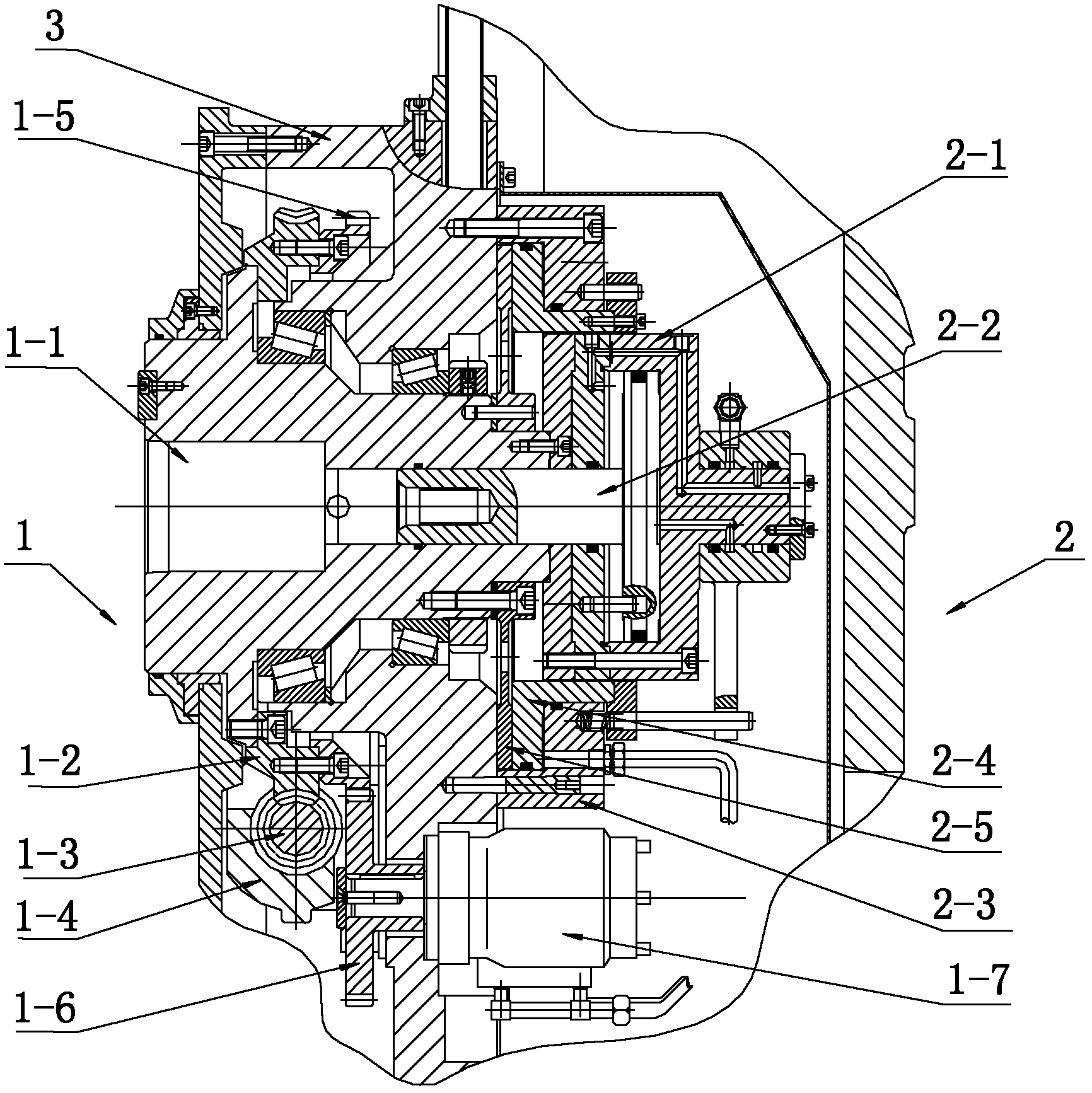
[0013] see figure 1 , CNC large-scale spiral bevel gear broaching machine indexing and clamping device, including an indexing mechanism 1 driven by a servo motor, the indexing mechanism includes a worm 1-3 connected to the output shaft of the servo motor through a coupling The two ends of the worm are supported and fixed in the worm bracket 1-4 through bearings, and the outer circle of the workpiece main shaft 1-1 is fixed with a worm wheel 1-2 engaged with the worm. On the worm gear 1-2 of the indexing mechanism, a large gear 1-5 is also fixed, and the large gear meshes with the pinion shaft 1-6, and the pinion shaft and the hydraulic motor 1-7 fixed in the spindle housing 3 Connect to form a hydraulic damping device. When the workpiece sp...


PUM


Abstract

The invention relates to an indexing and clamping device for a numerically-controlled large spiral bevel gear broaching machine. The device comprises an indexing mechanism driven by a servo motor, and is characterized by further comprising a hydraulic clamping mechanism. The hydraulic clamping mechanism comprises a workpiece clamping part and a main shaft clamping part, wherein the workpiece clamping part comprises a miniature hydraulic piston cylinder fixedly connected with one end of a workpiece main shaft; a piston rod of the miniature hydraulic piston cylinder is extended out of a cylinder body and into the workpiece main shaft; the head part of the piston rod is connected with a tension rod; the main shaft clamping part comprises a hydraulic cylinder sleeved outside the miniature hydraulic piston cylinder; a friction plate fixed with one end of the workpiece main shaft is arranged in the hydraulic cylinder; and a piston piece is arranged between the friction plate and the hydraulic cylinder. The device has the advantages that: a numerically-controlled indexing and auxiliary indexing damping device and an indexing hydraulic clamping device are adopted, so the indexing operation of a lathe is smoother, accurate and reliable, the slight reciprocation of a workpiece in a cutting process is avoided and gear machining accuracy is improved; and a large gear can be machined and the requirements for small quantities and many varieties in the industrial production of automobiles are met.

Description

technical field [0001] The invention belongs to the technical field of gear broaching machines, in particular to an indexing and clamping device of a numerically controlled large-scale spiral bevel gear broaching machine. Background technique [0002] As the key part of the transmission device, the bull wheel in the spiral bevel gear pair or the hypoid gear pair is widely used in various industries such as automobiles, tractors, construction machinery, and military industry. In the process of processing spiral bevel gears and hypoid gears, it is necessary to ensure that the errors of the tooth orientation, tooth shape, and tooth pitch of the gears are within a certain range of requirements, so as to ensure high transmission accuracy of the processed teeth. In the gear broaching machine in the prior art, during the workpiece cutting process, due to the frequent indexing action of the indexing mechanism, the required time is relatively short. When the worm gear meshes, the gap...

Claims


Application Information

Patent Timeline
Patent Type & Authority Applications(China)
IPC IPC(8): B23F23/08B23F23/06
Inventor 吴文仲经伟大
Owner TIANJIN NO 1 MACHINE TOOL WORKS
Learn More