
Novel fiber bunching device

A technology of fiber bundles and top rollers, which is applied in textiles and papermaking, drafting equipment, spinning machines, etc., can solve the problems of yarn hairiness, fly, and low fiber strength, and achieve less fly, less broken ends, The effect of high fiber strength

Active Publication Date: 2013-08-21
陆节
View PDF1 Cites 0 Cited by
  • Summary
  • Abstract
  • Description
  • Claims
  • Application Information

AI Technical Summary

Problems solved by technology

[0006] The technical problem to be solved by the present invention is to overcome the above-mentioned deficiencies and provide a fiber bundling device, which solves the problems of many yarn hairiness, low fiber strength and many flying flowers spun by spinning and wool spinning equipment, and reduces the production cost ,Improved work efficiency

Method used


Image

  • Novel fiber bunching device
  • Novel fiber bunching device
  • Novel fiber bunching device

Examples


Embodiment Construction

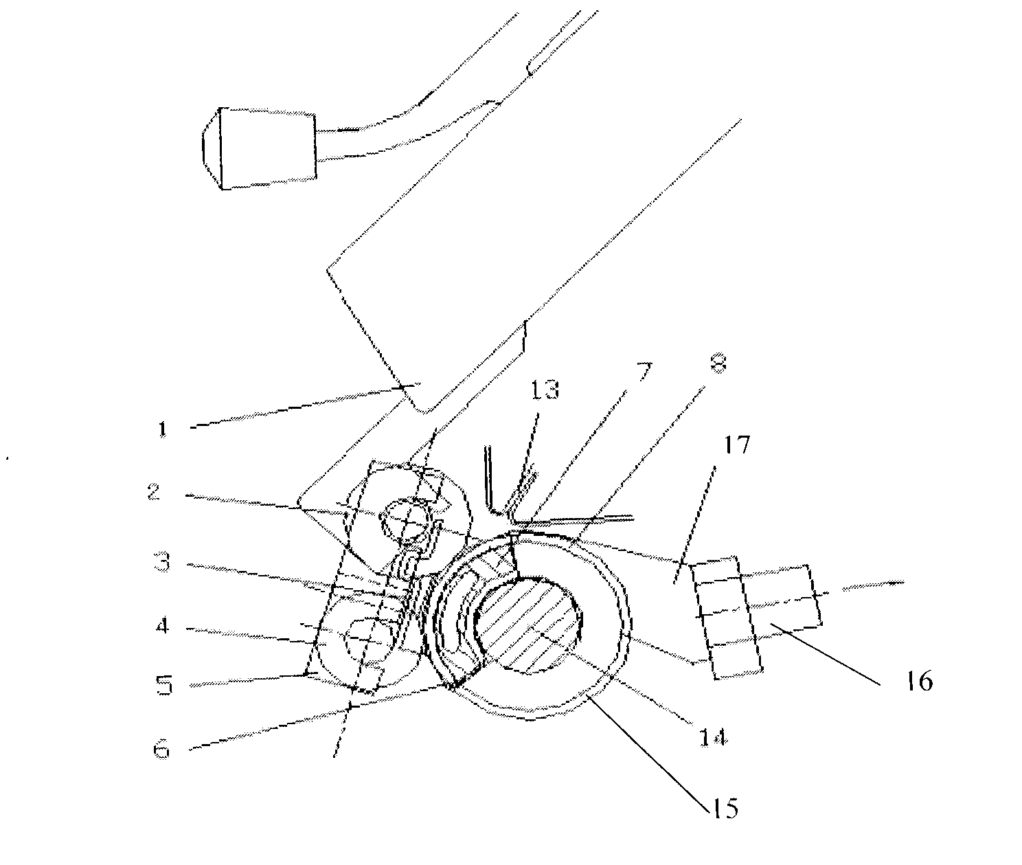
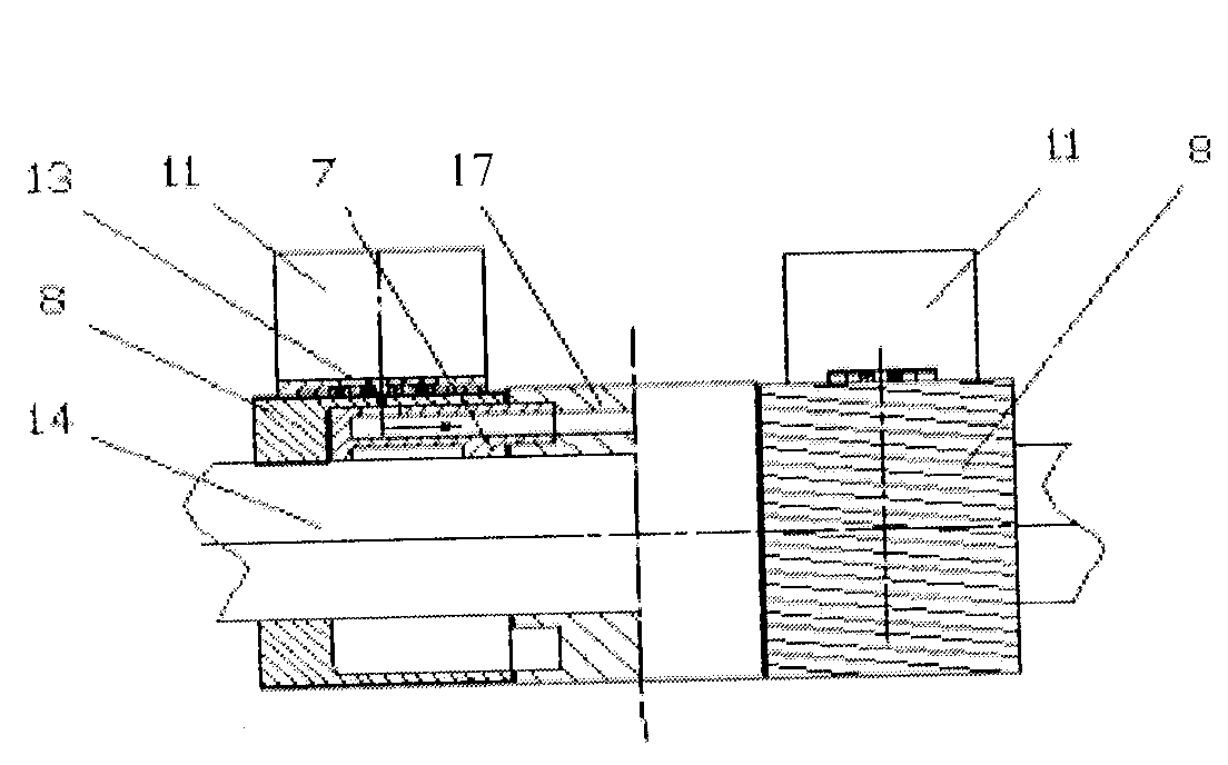
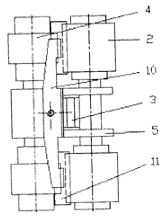
[0014] A fiber bundle device, which is composed of a double top roller assembly and a hollow roller assembly, the double top roller assembly is composed of a top roller frame 5, a spring 3, a positioning plate 10, an air flow orientation block 11, a permanent magnet 12, a first The top roller 2 and the second top roller 4 are composed, the first top roller 2 and the second top roller 4 are arranged on the top roller frame 5, the air flow orientation block 11 is arranged on the top roller frame 5 through the positioning plate 10, and the spring 3 is arranged on the top roller frame 5. On the top roller stand 5, the permanent magnet 12 is arranged on the air flow orientation block 11, the shape of the air flow orientation block 11 is made of a hyperboloid, a groove is opened at the lower end, and a hole is provided at the upper end; the hollow roller assembly is made of a hollow roller Ring 8, baffle plate 6, wide suction nozzle 7, main shaft 14, lower dust cover 15, suction seat...


PUM

PropertyMeasurementUnit
diameteraaaaaaaaaa
areaaaaaaaaaaa
diameteraaaaaaaaaa

Abstract

The invention relates to a fiber bunching device. In the device, a first top roller and a second top roller (4) are arranged on a cap bar (5); an airflow orientation block (11) is arranged on the cap bar (5) through a positioning plate (10); a spring (3) is arranged on the cap bar (5); a permanent magnet (12) is arranged on the airflow orientation block (11); a wide vacuum nozzle (7), a lower dustproof cover (15), a suction base (16), an upper dustproof cover (17) and a baffle plate (6) are arranged in hollow roller rings (8); the hollow roller rings (8) are arranged on a main shaft (14) pairwise; the wide vacuum nozzle (7) is provided with an upper dustproof cover (17); the lower part of the wide vacuum nozzle (7) is provided with a lower dustproof cover (15); the upper dustproof cover (17) is connected with the suction base (16); both sides of the upper dustproof cover (17) are provided with two rows of small holes; and the lower dustproof cover (15) is provided with a net. Due to the adoption of novel fiber bunching device, the problems of large quantity of feathers, low fiber strength and large amount of flies existing in yarns spun by using yarn spinning and wool spinning equipment are solved, the production cost is lowered, and the working efficiency is increased.

Description

technical field [0001] The invention belongs to a device on a textile machine, in particular to a fiber bundle device. Background technique [0002] Original spinning and wool spinning equipment: poor fiber aggregation, in a loose state, many fibers at the edge of the yarn are lost or attached to the yarn or twisted into the yarn in some form, resulting in yarn hairiness and miscellaneous , Bar uniformity is poor. Concentrating devices at home and abroad are mainly two types of products, the negative pressure converging type and the main machine converging type. The principle of converging is to reduce the yarn triangle area before spinning and twisting. [0003] Negative pressure net coil device: the representatives of this form are the products of Suessen of Germany and Toyota of Japan. This device is to add a special-shaped tube in front of the roller of the original spinning machine head. There is a chute about two millimeters wide on the special-shaped tube. The chute...

Claims


Application Information

Patent Timeline
Patent Type & Authority Patents(China)
IPC IPC(8): D01H5/72
Inventor 陆节杨远立陆陨
Owner 陆节
Learn More