Ink-jet printhead board, ink-jet printhead, and ink-jet printing apparatus

a printhead board and inkjet technology, applied in printing, inking apparatus, electrical equipment, etc., can solve the problems of reducing the image data transfer ability (operation speed) of an ink-jet printhead board, reducing the cost and size of preparing 5 v logic power supply for the printer main body, and difficult to simply optimize logic power supply voltage to 3.3 v

Inactive Publication Date: 2005-12-06
CANON KK
View PDF18 Cites 11 Cited by
  • Summary
  • Abstract
  • Description
  • Claims
  • Application Information

AI Technical Summary

Problems solved by technology

In recent years, it becomes disadvantageous to prepare 5 V for the logic power supply of the printer main body in terms of the cost and size along with improvements in IC technique and the use of a new interface.
However, it is difficult to simply optimize the logic power supply voltage to 3.3 V because the head board mixedly bears a logic circuit and a high-breakdown-voltage driver for driving a heater.
A decrease in the image data transfer ability (operation speed) of an ink-jet printhead board will be described as one of the problems.
As shown in FIG. 18B, the ability is poor at a logic power supply voltage of 3.3 V, and as the temperature rises, tends to further degrade.
In particular, the voltage fluctuation generated in the GND line of a driver transistor can cause a current driving malfunction.
The possibility of causing malfunctions along with the decrease in voltage increases in a circuit block for driving a driver transistor in accordance with the logic circuit.
In this situation, problems (a) and (b) occur when the printing apparatus is to cope with the decrease in voltage without changing the circuit arrangement on the board (HB).
The printing apparatus main body becomes bulky, which is disadvantageous to downsizing of the apparatus and increases the cost.
As a result, products become difficult to set on the current trend toward lower cost.
In this situation, the logic driving performance becomes poor, degrading the specification of the printing performance.
It, therefore, becomes difficult to maintain the image data transfer rate and meet needs for a higher transfer rate.
This may pose the following problem unique to the ink-jet printing apparatus.
In this case, an abnormal current flows through the heater element, resulting in element destruction and a fatal fault.
When conventional design conditions based on a voltage of 5 V are applied to the use of 3.3 V or lower, the functions of the logic and driver circuits are very difficult to implement.

Method used


Image

  • Ink-jet printhead board, ink-jet printhead, and ink-jet printing apparatus
  • Ink-jet printhead board, ink-jet printhead, and ink-jet printing apparatus
  • Ink-jet printhead board, ink-jet printhead, and ink-jet printing apparatus

Examples


first embodiment

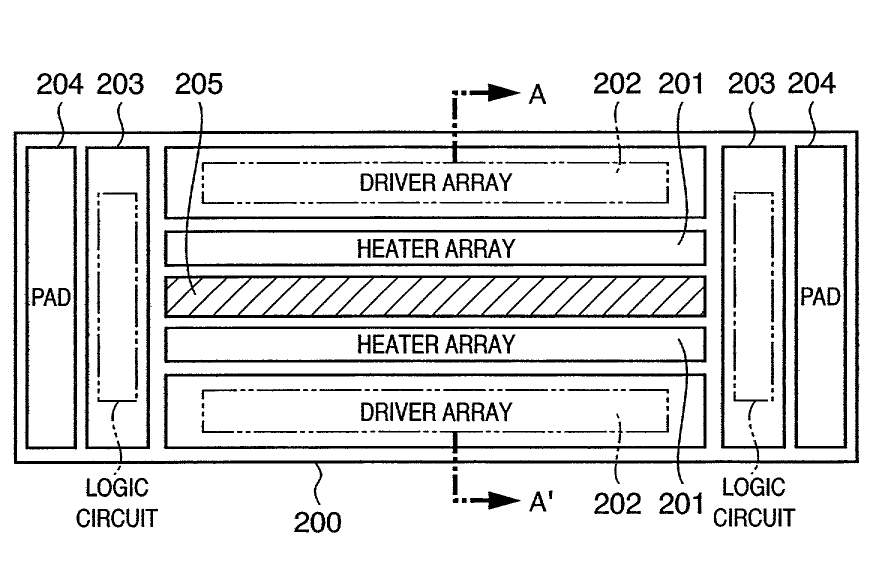
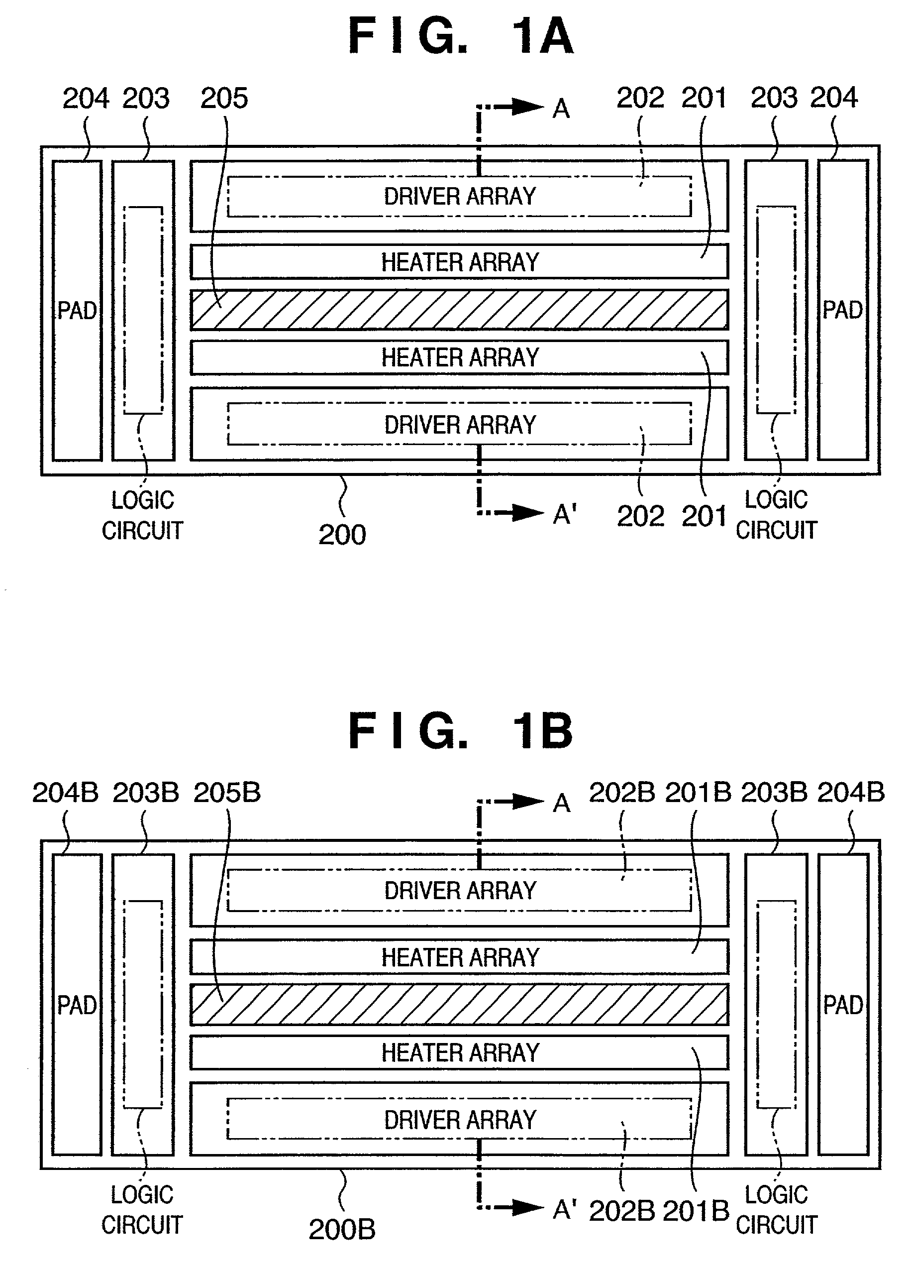
[0090]FIG. 1A shows a printhead board according to the Heater arrays 201 including 256-bit heaters, driver arrays 202 having drivers for driving the respective heaters, and logic circuits 203 for driving the drivers are formed on a single board 200. Pads 204 for electrically connecting the board to its outside are formed on the board 200.

[0091]FIG. 3 is a perspective view showing the outer appearance of an example of a printhead constituted using the printhead board according to the first embodiment. As shown in FIG. 3, the printhead has two lines of orifices 210 in correspondence with the heater arrays 201 arranged on the two sides of ink supply ports 205 shown in FIG. 1A. The orifices 210 are arranged in corresponding lines at a predetermined pitch on an orifice plate 206. The ink tank IT indicated by a two chain double-dashed line is detachably attached to the printhead of the first embodiment.

[0092]FIG. 4 is a schematic perspective view showing an example of an ink-jet printing...

second embodiment

[0122]To prevent the malfunction of a heater element and prevent an abnormal current from flowing, the second embodiment controls the operating voltage threshold of a transistor by using the channel impurity concentration NA in equation (1) as a key parameter in processing of step S1440 of FIG. 14. More specifically, the operation threshold of an enhancement NMOS transistor which constitutes a driver for driving a heater, and the operation threshold of an enhancement NMOS transistor which constitutes a logic circuit for driving the driver are changed as follows. The channel impurity concentration NA is changed to control the channel impurity concentrations of the two transistors so as to maintain the printing performance of the ink-jet printing apparatus.

[0123]From the relation in equation (1), the threshold Vth is higher for a higher channel impurity concentration NA.

[0124]2030 and 2040 in FIG. 2B are views schematically showing the NMOS transistors of the logic and driver circuit ...

third embodiment

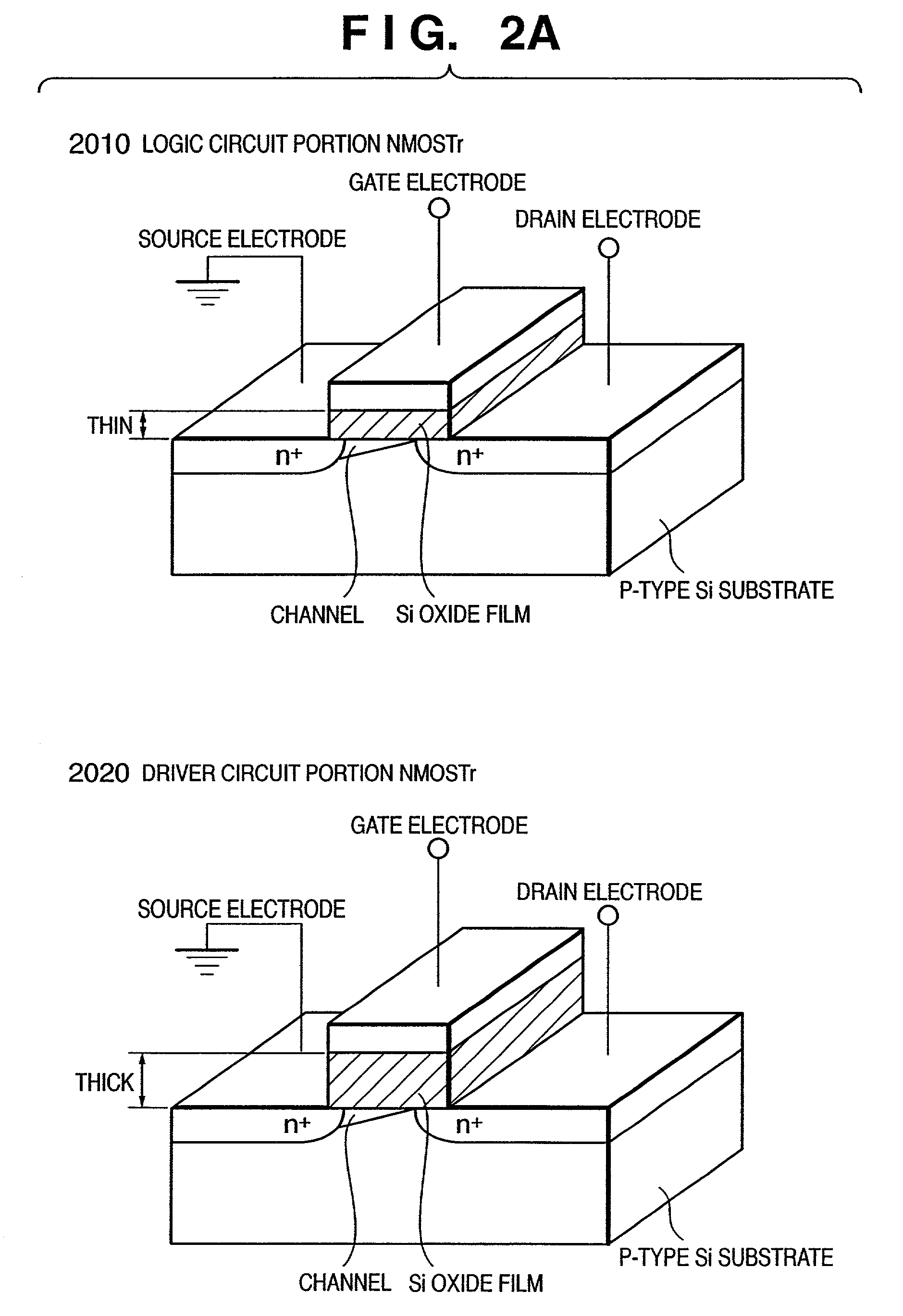
[0128]To prevent the malfunction of a heater element and prevent an abnormal current from flowing, the third embodiment controls the operating voltage threshold of a transistor by using control of the oxide film thickness TOX and the channel impurity concentration NA in equation (1) as key parameters in steps S1401 and S1440 of FIG. 14. More specifically, the operation threshold of an enhancement NMOS transistor which constitutes a driver for driving a heater, and the operation threshold of an enhancement NMOS transistor which constitutes a logic circuit for driving the driver are changed as follows. The oxide film thickness and channel impurity concentration NA are changed in a superposition manner to control the threshold voltages of the two transistors so as to maintain the desired printing performance of the ink-jet printing apparatus.

[0129]In FIG. 1B showing an ink-jet printhead board according to the third embodiment, heater arrays 201B including 512-bit heaters, driver arrays...


PUM


Abstract

A stable operation is realized without any malfunction of a driver even under a voltage condition that a supplied voltage is 3.3 V or lower. For this purpose, in an ink-jet printhead having an ink orifice for discharging ink, a plurality of heat generation elements for generating heat energy used to discharge ink, and an ink channel which incorporates the heat generation elements and communicates with the ink orifice, a driver for driving the heat generation elements, and a logic circuit for controlling the driver are formed on a single board. The gate oxide film thickness of an enhancement NMOS transistor which forms the driver is larger than that of an enhancement NMOS transistor which forms the logic circuit.

Description

FIELD OF THE INVENTION[0001]The present invention relates to a printhead board, a printhead using the board, and a printing apparatus on which the printhead is mounted.BACKGROUND OF THE INVENTION[0002]Ink-jet printing is a printing method with a more prominent feature than other printing methods because of little printing noise and high-speed printing.[0003]In the printhead of a conventional printing apparatus which adopts this printing method, orifices formed to discharge a liquid such as ink, and electrothermal transducers (heaters) which communicate with the orifices and generate, as energy generation elements for discharging ink, predetermined heat energy in order to heat and discharge droplets of ink or the like are arranged on a printhead element board (to be also referred to as a heater board “HB”).[0004]Further, a plurality of drivers for driving the respective heaters, a memory which temporarily stores printing data input from a printing apparatus in order to transfer seria...

Claims


Application Information

Patent Timeline
Patent Type & Authority Patents(United States)
IPC IPC(8): B41J2/05B41J2/135H01L21/8234H01L27/088
CPCB41J2/04518B41J2/0452B41J2/04541B41J2/04543B41J2/0455B41J2/0458B41J2/04581B41J2202/13B41J2/135
Inventor SAITO, ICHIROFURUKAWA, TATSUOIMANAKA, YOSHIYUKIHIRAYAMA, NOBUYUKIMOCHIZUKI, MUGAYAMAGUCHI, TAKAAKI
Owner CANON KK
Why Eureka
Try Eureka