Active coherence reduction for interferometer interrogation

a technology of active coherence and interferometer, which is applied in the direction of converting sensor output, measuring devices, instruments, etc., can solve the problems of adding noise to the signal of sensors with sensor delays, and achieve the effect of confined peak in the coherence function, uniform optical spectrum spread, and broadened optical spectrum

Active Publication Date: 2008-10-07
OPTOPLAN
View PDF12 Cites 15 Cited by
  • Summary
  • Abstract
  • Description
  • Claims
  • Application Information

AI Technical Summary

Benefits of technology

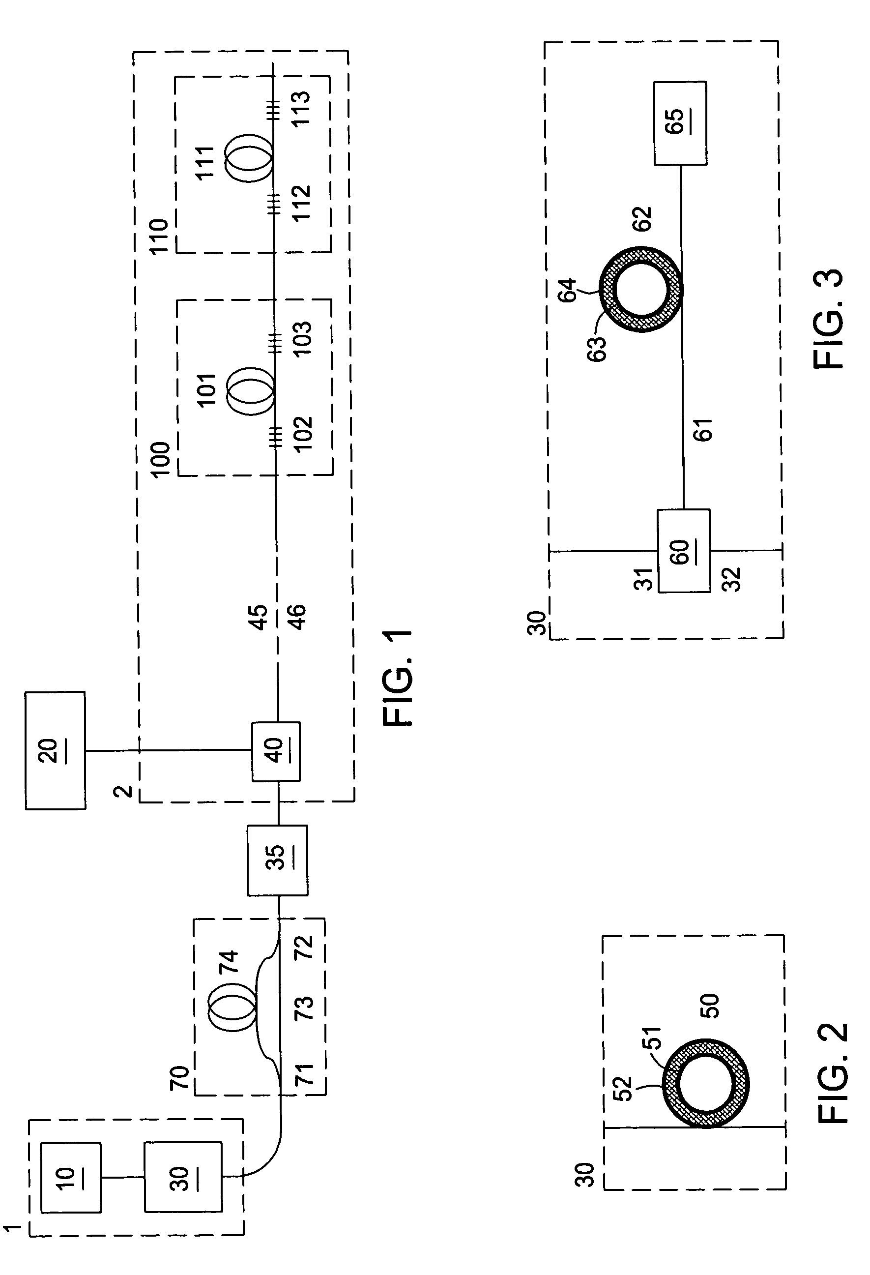
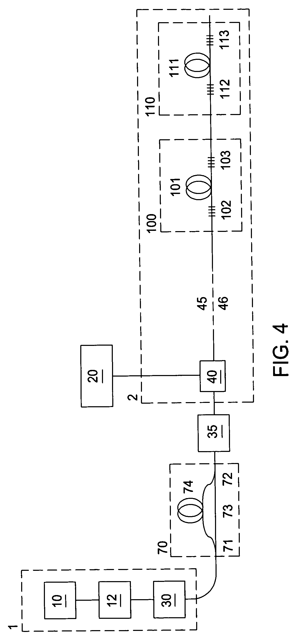
[0033]The invention provides a method for reducing noise and harmonic distortion due to unwanted reflection such as Rayleigh scattering, reflections from other sensors multiplexed on the same fiber, connectors, etc. The invention also provides a method that increases the threshold for Stimulated Brillouin Scattering (SBS). This enables more optical power to be launched into the optical network, when the optical power of the source is limited by SBS. The reduction of noise and harmonic distortion and the increase of the SBS threshold are achieved by reducing the coherence of a highly coherent optical source by coherence modulation means that modulates the output field phasor of each channel to produce a broadened optical source power spectrum.
[0034]The coherence modulation means reduces the autocorrelation of the source, where the autocorrelation function of a wavelength channel is defined as the Fourier transform of the optical source power spectrum in one wavelength channel, where the optical power spectrum is defined with a resolution bandwidth similar to the necessary detection bandwidth. Alternatively, the autocorrelation function of a wavelength channel from the source versus delay may be defined as a filter impulse response convolved with the product of the conjugate of output field phasor and the output field phasor delayed by the given delay, where the filter impulse response has a frequency representation with a bandwidth similar to the necessary detection bandwidth. The coherence time may be defined as the full width at half maximum (FWHM) of the autocorrelation function. The coherence time is inversely proportional to the bandwidth of the optical source power spectrum. An efficient coherence modulation means for use in combination with a compensating interferometer will produce an output field phasor with a coherence time that is significantly shorter than the sensor delay. If the coherence time is sufficiently short, signal components that appear due to interference formed between optical pathways, with a delay different from the sensor delay of the interrogated interferometer, will be substantially suppressed. If a compensating interferometer is not used, significant improvements can still be achieved by reducing the coherence time from that of a highly coherent laser source to a coherence time that is reduced but longer than the sensor interferometer delay, without disturbing the mean source frequency.
[0035]It is essential that the coherence modulation means produce an autocorrelation function that is stable versus time. If this is not the case, noise will be added on the signal from sensors with sensor delays that are not completely matched with the maximum of the autocorrelation function. The stability of the autocorrelation function within the necessary detection bandwidth can be achieved by modulating the output field phasor of each wavelength channel from the source in a periodic manner with a cycle frequency that is larger than the necessary detection bandwidth. Alternatively, stability of the autocorrelation function can be achieved by modulation of the output field phasor of each wavelength channel from the source in a periodic manner with a cycle frequency that is phase-locked to a demodulation carrier frequency, such as the phase generated carrier (PGC) modulation frequency in a system employing PGC demodulation or the heterodyne frequency in a system employing heterodyne demodulation.
[0037]Coherence modulation means that produces a broadened optical spectrum may be achieved by direct modulation of the source laser for each wavelength channel. If the source laser is a fiber laser, direct modulation can be achieved by periodic strain modulation of the fiber laser. If the source laser is a diode laser, direct modulation can be achieved by periodic modulation of the drive signal of the diode laser, and the modulation signal may have triangular waveform. If the source laser is a wavelength tunable diode laser, direct modulation can be achieved by periodic modulation of one or more control signals to the wavelength tunable diode laser, and the laser wavelength may have triangular waveform. A triangular waveform provides a more uniform spread of the optical spectrum than a pure sine modulation, and thus more confined peak in the coherence function with less sidelobes.
[0038]Coherence modulation means that produces a broadened optical spectrum may also be achieved by using an optical modulator that takes light output from at least one coherent light source as input and modulates the field phasor of the light before it is output from the modulator. Light from a multiple of coherent light sources operating at different wavelength channels may be combined with a wavelength division multiplexer and input to a common optical modulator, which modulates all wavelength channels simultaneously. This may provide a more cost effective solution than to use one modulator for each wavelength source. The optical modulator may be one out of an optical phase modulator, an optical amplitude modulator or an acousto-optical modulator. An optical phase modulator may comprise an optical fiber wound around a piezoelectric ring modulator, for example a lead titanate zirconate (PZT) ring modulator. In order to reduce polarization effects, the optical fiber may be twisted High Birefringence fiber or polarization maintaining fiber, where the input polarization to the polarization maintaining fiber is polarized along one of the polarization maintaining fiber eigenaxes. The optical phase modulator may also be an electro-optical phase modulator such as a lithium niobate phase modulator. Lithium niobate phase modulators have the advantage of a much higher speed than most other types of optical modulators, and much shorter coherence lengths can therefore be achieved with such a device than with for example an acousto-optic modulator. The phase modulator may modulate the phase of the output field phasor of each wavelength channel with a repeated pseudorandom pattern switching between two phase-shift values that are separated by π radians. Other modulation patterns may also be employed. For a PZT ring modulator a sine modulation at a mechanical resonance frequency of the PZT ring may be desirable.

Problems solved by technology

If this is not the case, noise will be added on the signal from sensors with sensor delays that are not completely matched with the maximum of the autocorrelation function.

Method used


Image

  • Active coherence reduction for interferometer interrogation
  • Active coherence reduction for interferometer interrogation
  • Active coherence reduction for interferometer interrogation

Examples


Embodiment Construction

[0047]The combination of a low coherence source and a compensating interferometer may also be used in systems employing continuous wave (CW) source interrogation rather than pulsed source interrogation. If a compensating interferometer is used in combination with a phase generated carrier (PGC) technique, the PGC cannot be induced by modulating the source directly. However, it may be induced by a phase modulator placed in one of the arms of the compensating interferometer, or by modulation of the optical frequency of the light between the output of the compensating interferometer and the input to the lead fiber. The PGC can also be generated by modulating the delay in one of the interferometer arms, provided that these positions are accessible.

[0048]A basic idea of the present invention is to modulate the complex field amplitude of the signal interrogating an optical interferometer in such a way that the temporal coherence is reduced, thus reducing the sensitivity to unwanted reflec...


PUM


Abstract

Methods and apparatus reduce coherence of an optical signal that is used to interrogate optical interferometric sensors. The optical field phasor of the interrogation source is modulated in a controlled manner to produce a broadened optical source power spectrum at the output of the source unit. The output from the source unit is launched into an optical sensor network, comprising a multiple of optical pathways from its input to the detection unit, where pairs of optical pathways form sensor interferometers. A compensating interferometer with delay difference similar to the sensor delay difference may be arranged in a serially coupled manner with the optical sensor network, either before or after the network. The coherence modulation may be performed through direct modulation of the source or through external modulation of the light with piezoelectric ring modulator, a Lithium niobate phase or intensity modulator, or an acoustooptic modulator.

Description

CROSS-REFERENCE TO RELATED APPLICATIONS[0001]This application claims benefit of U.S. provisional patent application Ser. No. 60 / 510,188, filed Oct. 10, 2003, which is herein incorporated by reference.BACKGROUND OF THE INVENTION[0002]1. Field of the Invention[0003]The present invention relates to interferometric optical sensor systems employing active coherence reduction of the source light.[0004]2. Description of the Related Art[0005]The coherence function of an optical signal versus delay τ and time t is defined as the autocorrelation function of the normalized field phasor E(t) of the optical signal. In other words, the coherence function R(τ,t) equals the autocorrelation function of the light and is given by[0006]R⁡(τ,t)=∫t-T2t+T2⁢E*⁡(t′)⁢E⁡(t′+τ)⁢w⁡(t′-t)⁢ⅆt′(1)In the common mathematical definition of the coherence function the integration time T in equation (1) approaches infinity, while w(t) is independent on t and equals 1 / T. If two optical field phasors E(t) and E(t+τ) origi...

Claims


Application Information

Patent Timeline
Patent Type & Authority Patents(United States)
IPC IPC(8): G01B9/02G01D5/353
CPCG01D5/35312G01B9/02049G01D5/353G01D5/35303
Inventor RONNEKLEIV, ERLENDWAAGAARD, OLE HENRIKBLOTEKJAER, KJELLTHINGBO, DAGLOVSETH, SIGURDKUNDSEN, SVERRE
Owner OPTOPLAN
Why Eureka
Try Eureka