Solid state disk for rapidly storing and displaying massive image data

A technology for image data and rapid storage, applied in electrical digital data processing, memory address/allocation/relocation, instruments, etc., can solve the problems of fast access to massive data, slow speed, and limited memory capacity that cannot be fundamentally solved. Achieve faster storage and access and display, better integration, and better organization

Inactive Publication Date: 2012-02-22
NAT UNIV OF DEFENSE TECH
View PDF3 Cites 14 Cited by
  • Summary
  • Abstract
  • Description
  • Claims
  • Application Information

AI Technical Summary

Problems solved by technology

However, due to the inherent shortcomings of the disk itself (such as slow speed, poor random access performance, etc.), although the storage capacity can meet the storage requirements of the system, the speed is far from meeting the requirements.
The method of quickly displaying massive image data mainly uses memory m

Method used


Image

  • Solid state disk for rapidly storing and displaying massive image data
  • Solid state disk for rapidly storing and displaying massive image data
  • Solid state disk for rapidly storing and displaying massive image data

Examples


Embodiment Construction

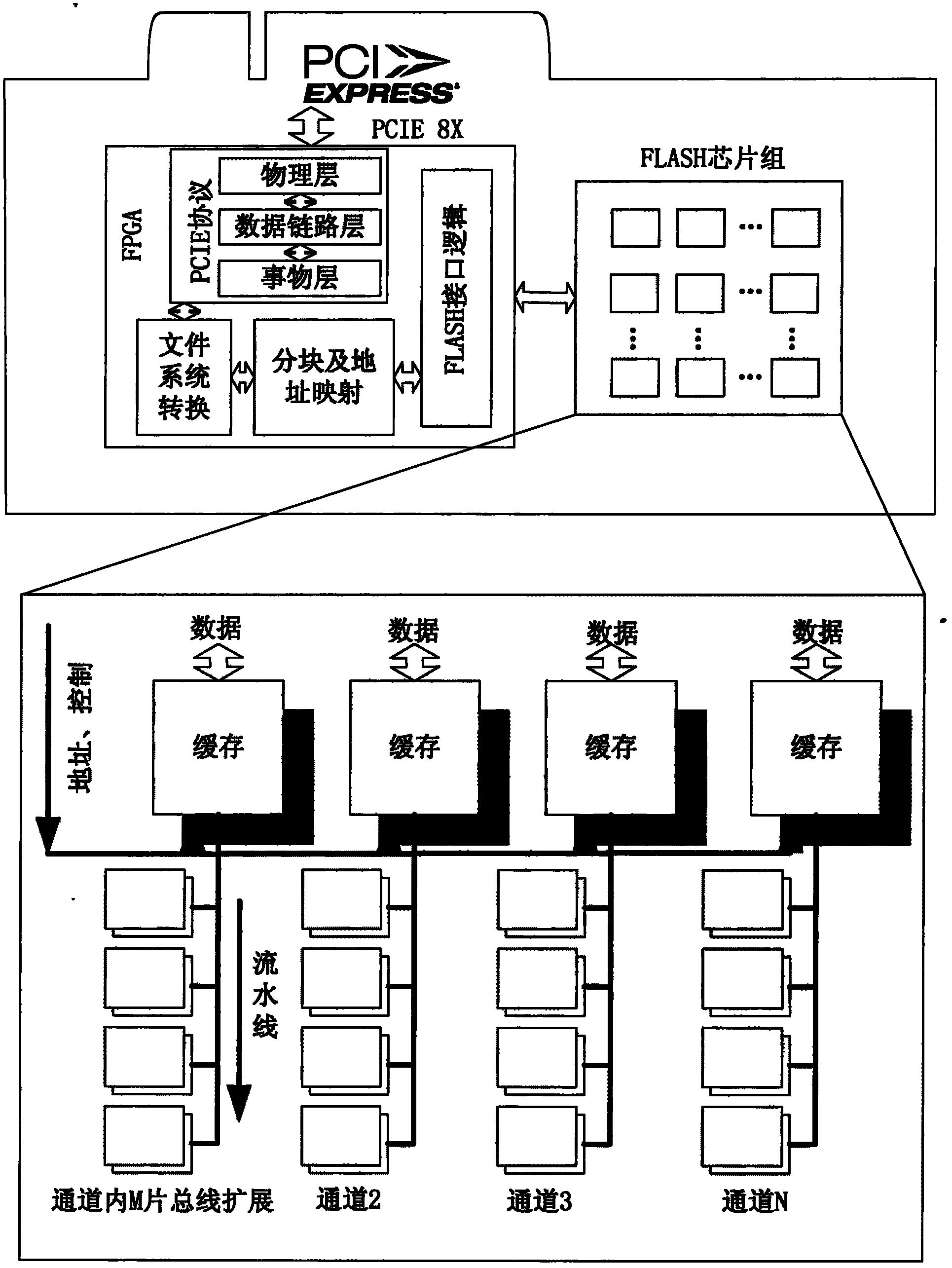
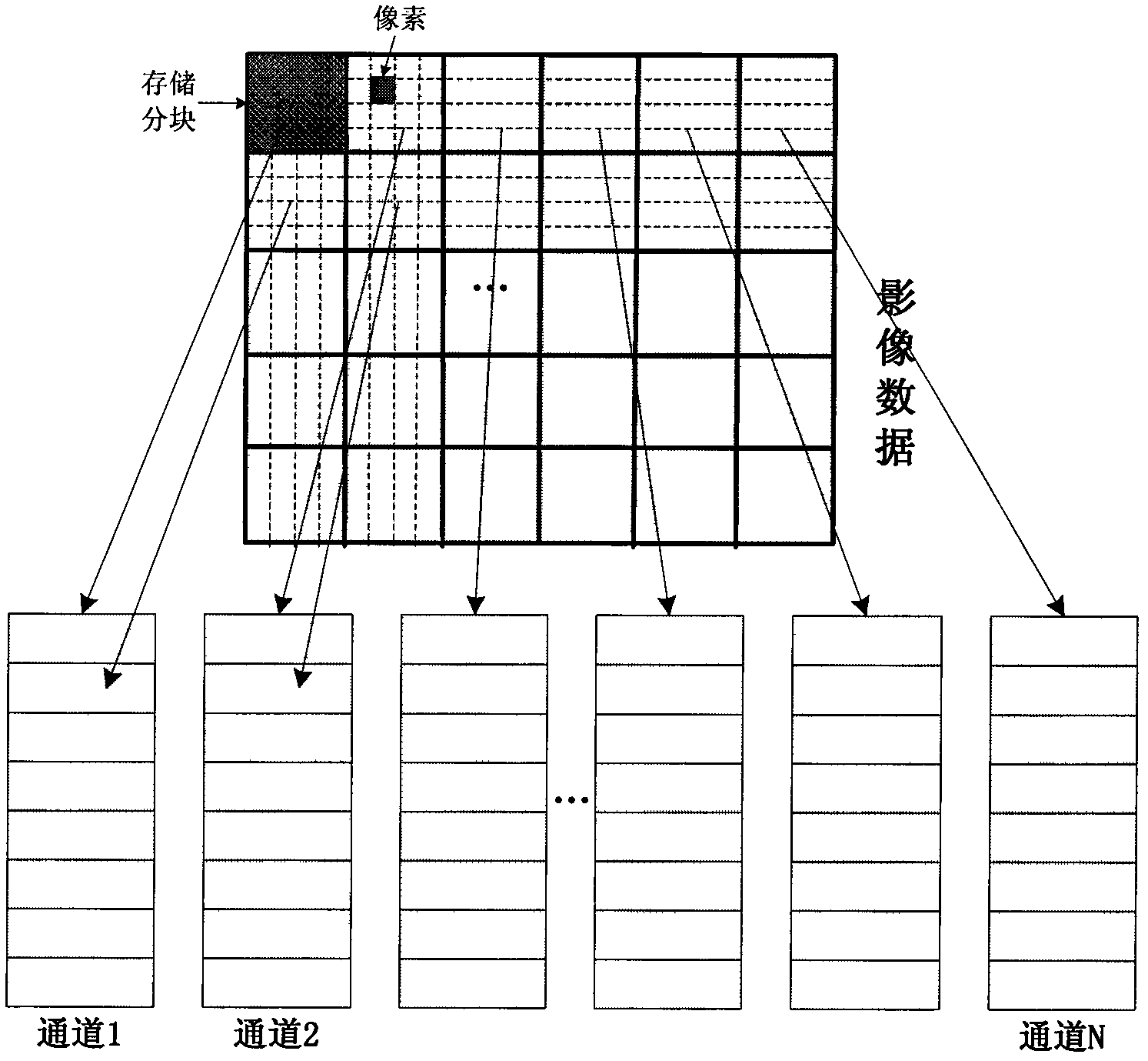
[0022] The specific implementation of massive image data storage hard disk mainly includes two parts: the implementation of hardware architecture and the implementation of software architecture. The implementation of the hardware architecture mainly includes PCIE interface design, FPGA circuit design, the organization of the storage medium FLASH and the interconnection between the above three parts; the implementation of the software architecture mainly includes the implementation of the PCIE protocol, file system conversion, image segmentation and Address mapping and FLASH interface logic design, etc.

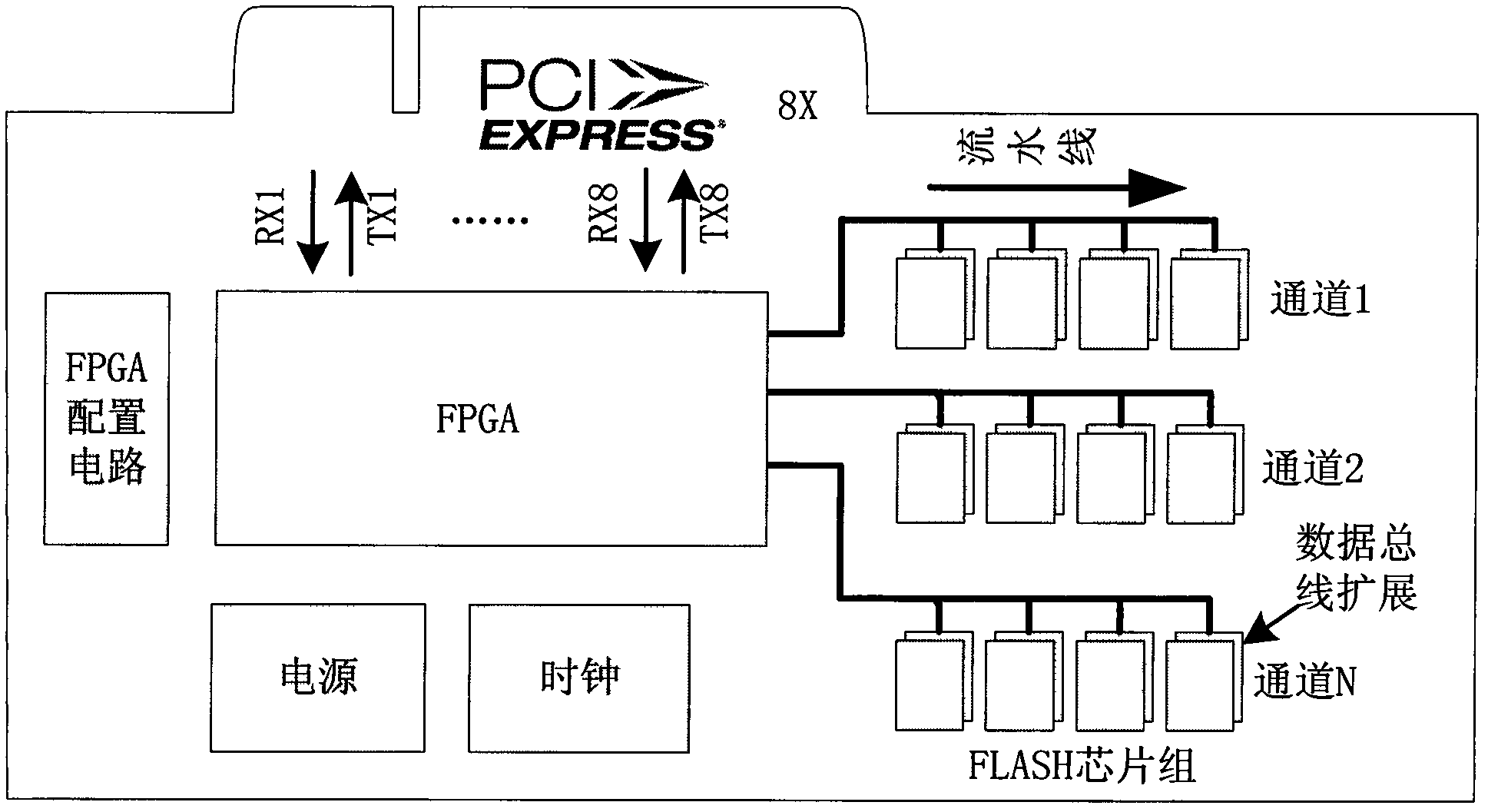
[0023] The specific implementation of the hardware architecture

[0024] The specific implementation of the hardware architecture is to provide signal paths for the system and ensure efficient interconnection between multiple chips of FLASH. It mainly includes PCIE interface design, FPGA circuit design, organization of storage medium FLASH and interconnection between the abov...


PUM


Abstract

The invention relates to a solid state disk for rapidly storing and displaying massive image data, which comprises a hardware architecture and a software algorithm for rapidly storing and displaying the massive image data. On the hardware architecture, solid state storage medium is reasonably and efficiently organized through comprehensive utilization of a channel internal bus extension technology, a channel internal pipelining technology and a multichannel parallel technology, so that the access speed of the storage medium is improved, and the data-transfer capacity of a system is improved through utilizing a PCIE (Peripheral Component Interconnect Express) interface to transfer data; and on a software architecture, rapid storage and display of the image data is mainly realized through a blocking storage and address mapping technology of the image data. The channel internal bus extension technology, the channel internal pipelining technology and the multichannel parallel technology are comprehensively utilized aiming at the characteristics of the massive image data, so that the organization of FLASH is more reasonable and efficient.

Description


Claims


Application Information

Patent Timeline
Owner NAT UNIV OF DEFENSE TECH
Why Eureka
Try Eureka