

Interconnect sheet, solar cell with interconnect sheet, solar module, and method of producing solar cell with interconnect sheet
A technology of solar cells and wiring boards, which is applied in the direction of electrical components, chemical instruments and methods, circuits, etc., can solve the problems of position deviation between wiring boards and back electrode type solar panels, wiring position deviation, etc., and achieve the purpose of suppressing poor insulation, The effect of suppressing the reduction of contact resistance and suppressing positional deviation
- Summary
- Abstract
- Description
- Claims
- Application Information
AI Technical Summary
Problems solved by technology
Method used
Image

Examples
Embodiment 1
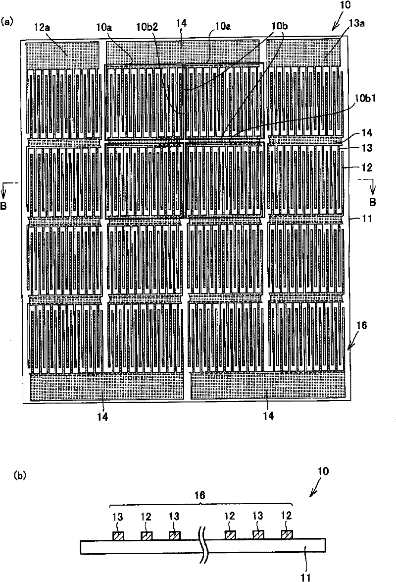
[0159] First, a PET film having a width of 510 mm, a length of 400 mm, and a thickness of 50 μm was prepared as an insulating base material of the wiring board. Next, copper foil with a thickness of 35 μm was bonded to the entire surface of one surface of the PET film. The adhesive was applied to one side of the PET film, the copper foil was laminated, and pressure and heat were applied to bond them together.
[0160] Next, part of the copper foil on the surface of the PET film is etched and patterned as figure 1 In the shape shown in (a), the following wiring 16 is formed. This wiring 16 includes a comb-shaped n-type wiring 12, a comb-shaped p-type wiring 13, and a comb-shaped n-type wiring 12 and a comb. The strip-shaped connection wiring 14 is electrically connected to the p-type wiring 13 . At the same time, when the wiring board is made as a solar battery unit or a solar battery module with a wiring board, the connection wiring 14 ( figure 1 10b1 ( figure 1 (a), ...
Embodiment 2
[0167] In Example 1, the wiring board and the back electrode type solar cell were bonded using a resin composition, and then sealed with a sealing material to produce a solar cell module. However, in Example 2, the wiring board was not bonded to the back surface. The electrode-type solar cells are bonded and sealed with a sealing material to produce a solar cell module.
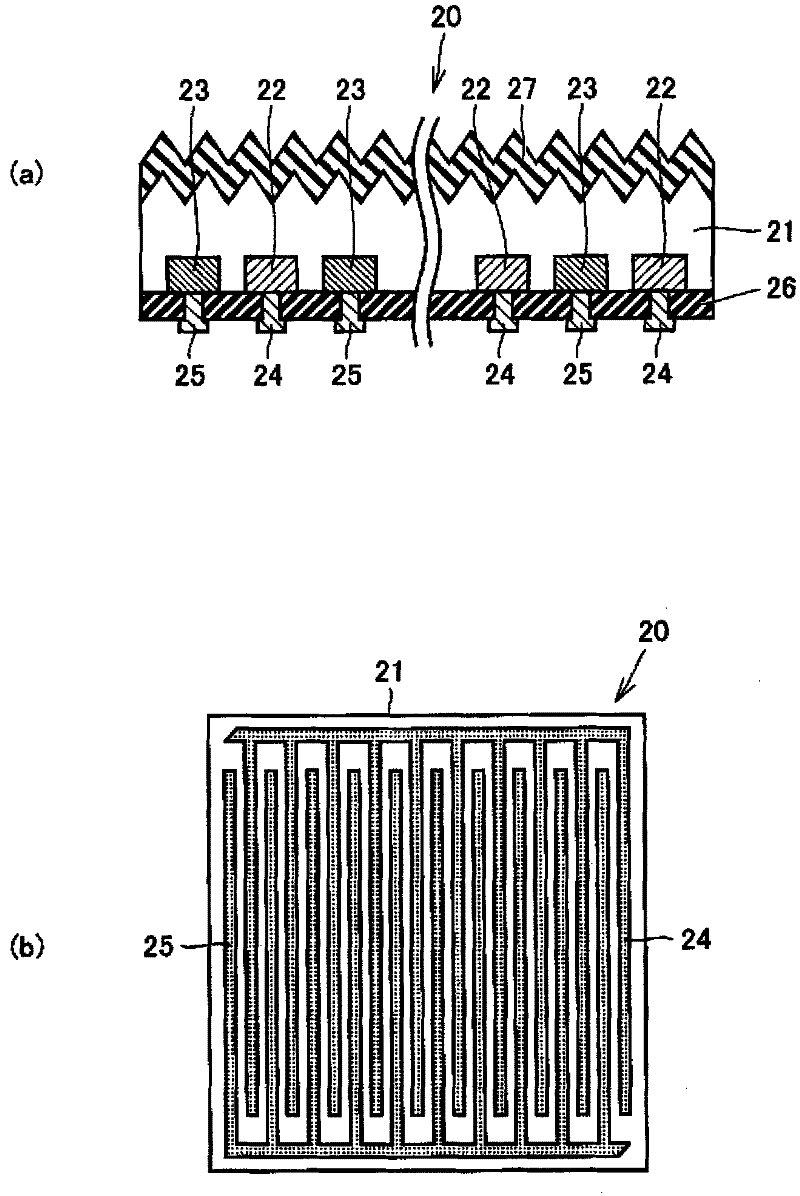
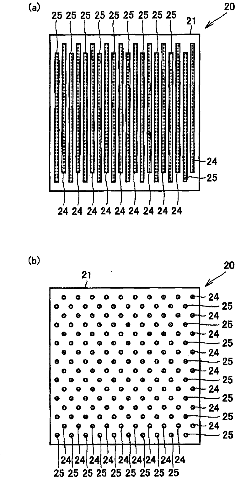
[0168] Here, only the differences from Embodiment 1 will be described. The procedure was the same as in Example 1 until each of the twelve back electrode type solar cells 20 was installed on the interconnection sheet 10 .
[0169] Next, the thus laminated wiring board and solar cell were placed between the ethylene vinyl acetate resin (EVA resin) provided on the glass substrate and the EVA resin provided on the PET film. Then, using a laminator, the EVA resin on the side of the glass substrate is crimped to the back electrode type solar cell unit 20 of the solar cell with a wiring sheet, and the EVA resin on...
PUM
 Abstract
Description
Claims
Application Information