
Imaging apparatus and imaging method

A technology of a camera device and a camera element, which is applied in photography, image communication, stereo photography, etc., can solve the problems of image quality degradation, high cost, and acquisition of space models, and achieves simple position adjustment, wide focus adjustment range, high image quality effect

Inactive Publication Date: 2012-02-29
SHARP KK
View PDF9 Cites 4 Cited by
  • Summary
  • Abstract
  • Description
  • Claims
  • Application Information

AI Technical Summary

Problems solved by technology

[0017] However, in the imaging lens devices of Patent Documents 1 to 3, since the adjustment accuracy of the relative position of the optical system and the imaging element affects the image quality, there is a problem that the relative position of the optical system and the imaging element needs to be adjusted accurately during assembly.
In addition, in the case of adjusting the relative position only with mechanical precision, a high-precision non-solid lens and the like are required, resulting in a problem of high cost.
In addition, even if the relative position of the optical system and the imaging element is correctly adjusted when the device is assembled, the relative position of the optical system and the imaging element may change due to changes in usage time, etc., and image quality may deteriorate.
The image quality will improve if the position is adjusted again, but there is a problem that the same adjustment as when assembling is required
In addition, in a device with a plurality of optical systems and imaging elements, since there are many positions to be adjusted, there is also a problem that a long working time is required.
[0018] In addition, in the image generation method and device of Patent Document 4, in order to generate a viewpoint-converted image, it is necessary to generate an accurate spatial model, but there is a problem that it is difficult to accurately obtain stereoscopic information such as a spatial model from a stereoscopic image.
In particular, in distant images where the parallax of the stereoscopic image is small, it is difficult to accurately obtain stereoscopic information such as a spatial model according to the stereoscopic image due to the influence of image brightness changes or noise.
Therefore, even if a super-sharp image is generated in a specific area where the parallax of the stereoscopic image is small, it is difficult to map it to the space model with high precision.

Method used


Image

  • Imaging apparatus and imaging method
  • Imaging apparatus and imaging method
  • Imaging apparatus and imaging method

Examples


Embodiment Construction

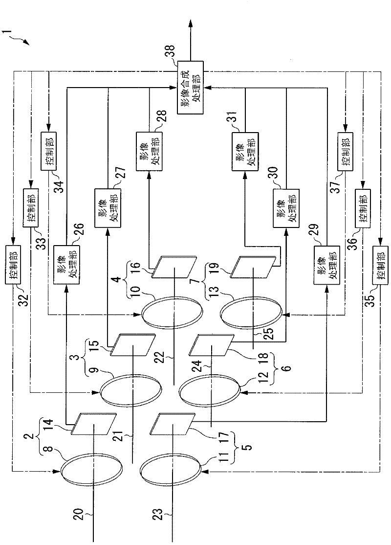
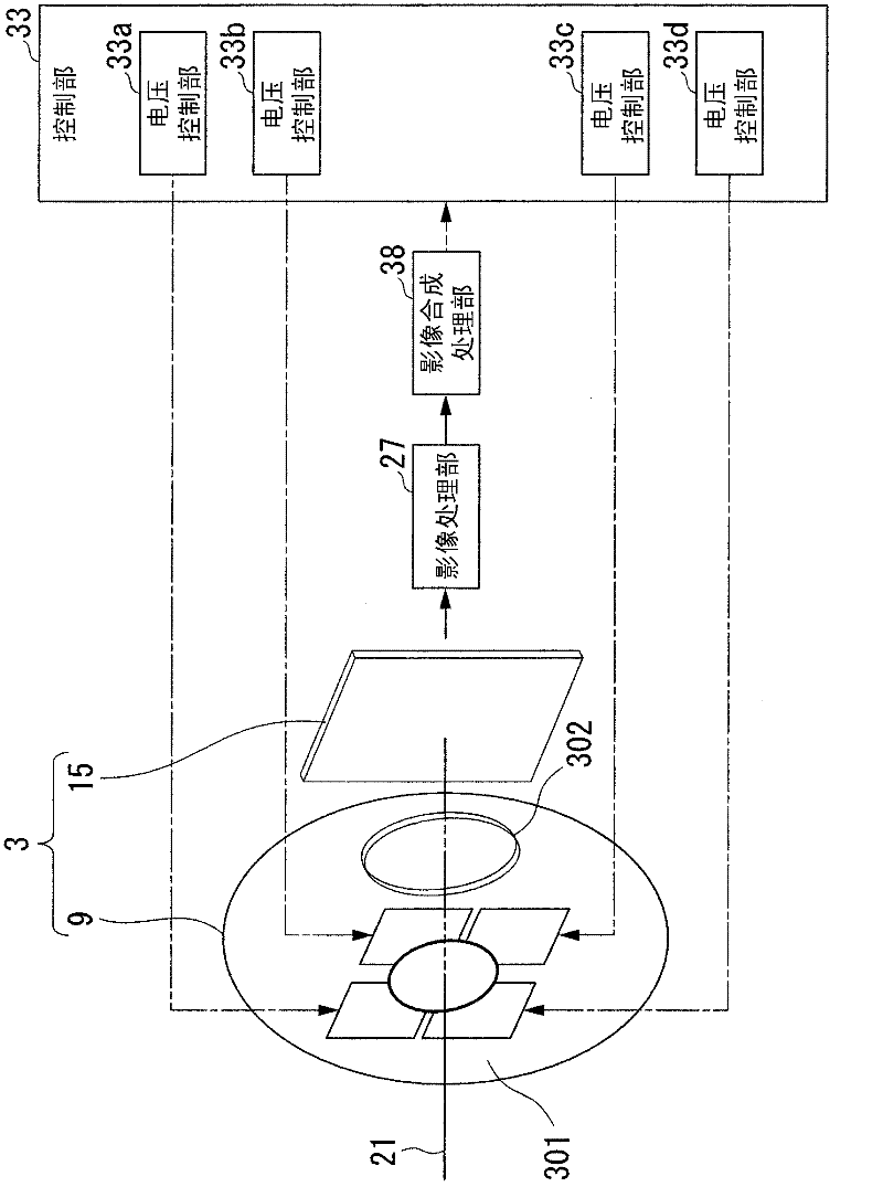
[0077] Hereinafter, embodiments of the present invention will be described in detail with reference to images. figure 1 It is a functional block diagram showing the overall configuration of the imaging device according to the first embodiment of the present invention. figure 1 The illustrated imaging device 1 includes six systems of unit imaging units 2 to 7 . The unit imaging unit 2 is composed of an imaging lens 8 and an imaging element 14 . Similarly, the unit imaging unit 3 is composed of an imaging lens 9 and an imaging element 15 . The unit imaging unit 4 is composed of an imaging lens 10 and an imaging element 16 . The unit imaging unit 5 is composed of an imaging lens 11 and an imaging element 17 . The unit imaging unit 6 is composed of an imaging lens 12 and an imaging element 18 . The unit imaging unit 7 is composed of an imaging lens 13 and an imaging element 19 . Each of the imaging lenses 8 to 13 forms an image of light from an imaging subject on each of th...


PUM


Abstract

An imaging apparatus provided with: a plurality of imaging elements; a plurality of solid lenses which form images on the plurality of imaging elements; a plurality of optical axis control units which control the directions of the optical axes of the light beams incident on the plurality of imaging elements; a plurality of video processing units which convert the photoelectric converted signals output by the plurality of imaging elements into video signals; a stereo image processing unit which, based on the plurality of video signals converted by the plurality of video processing units, carries out stereo matching processing to find the shift amount for each pixel, and generates compositing parameters in which the shift amounts exceeding the pixel pitch of the plurality of imaging elements are normalized by the pixel pitch; and a video compositing processing unit which combines the video signals converted by each of the plurality of video processing units based on the compositing parameters generated by the stereo image processing unit, and thereby generates high definition video.

Description

technical field [0001] The present invention relates to an imaging device and an imaging method. [0002] this application claims priority based on Japanese Patent Application No. 2009-083276 for which it applied to Japan on March 30, 2009, and uses the content here. Background technique [0003] In recent years, high-quality digital still cameras and digital video cameras (hereinafter, referred to as digital cameras) have rapidly spread. In addition, along with miniaturization and thinning of digital cameras, small high-quality digital cameras are mounted on mobile phone terminals and the like. An imaging device representing a digital camera is composed of an imaging element, an imaging optical system (lens optical system), an image processor, a buffer memory, a flash memory (card-type memory), an image monitor, and circuits and mechanisms for controlling these components. Solid-state electronic devices such as CMOS (Complementary Metal Oxide Semiconductor) sensors and CC...

Claims


Application Information

Patent Timeline
Patent Type & Authority Applications(China)
IPC IPC(8): H04N5/225G03B35/08G06T3/00H04N1/387H04N5/232
CPCG03B35/08H04N1/387H04N13/243H04N23/45H04N23/60H04N23/951H04N23/698H04N25/41
Inventor 佐藤俊一
Owner SHARP KK
Learn More