Dedusting device and dedusting method therefor

A technology of dust removal device and atomization device is applied in the field of industrial dust removal device and cyclone dust removal device to achieve the effect of saving water consumption, reducing energy consumption, and having little influence on physical and chemical properties.

Inactive Publication Date: 2012-03-21
LANZHOU UNIVERSITY
View PDF4 Cites 20 Cited by
  • Summary
  • Abstract
  • Description
  • Claims
  • Application Information

AI Technical Summary

Problems solved by technology

Because the bag filter has high dust removal efficiency and flexible use, the processing air volume can range from millions of cubic meters per hour to hundreds of thousands of cubic meters per hour, and the operation is relatively stable. Compared with the electrostatic precipitator, the initial investment is less and the maintenance is convenient. , combined with the ultrasonic atomization device used in combination, the technology of this patent application can overcome the shortcomings of the direct spray method, but there are still inherent shortcomings of the bag filter

Method used


Image

  • Dedusting device and dedusting method therefor
  • Dedusting device and dedusting method therefor
  • Dedusting device and dedusting method therefor

Examples


Embodiment 1

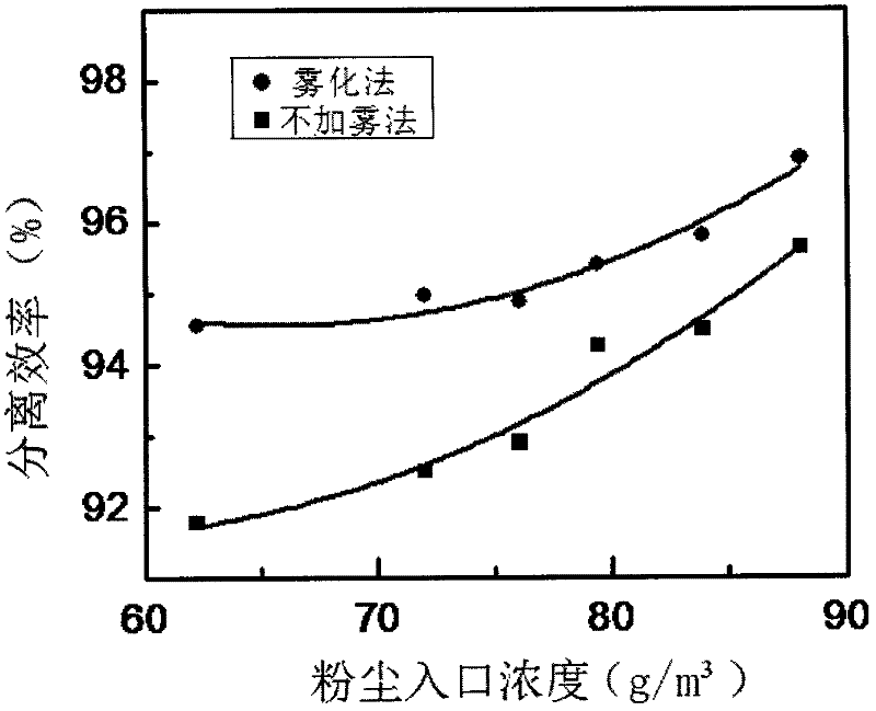
[0035] In this embodiment, the cement raw meal is used as the dust to be used, and the dust concentration is 66.22, 72.00, 76.06, 79.39, 83.89, 88.06g / m 3 The experiment was carried out at a temperature of 25°C.

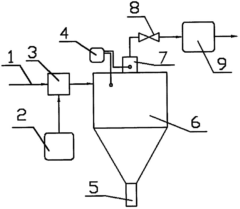
[0036] The experimental process is: open the ventilator 9, the wind speed is controlled by the valve 8 to 20m / s, the dusty gas is passed through the pipeline 1 into the cyclone separator 6 for separation, the clean gas is discharged through the air outlet 7, and the separated dust particles are discharged from the dust outlet. 5 discharge, the separation efficiency of different dust inlet concentrations by the non-fogging method is obtained from the amount of feed and output, and is drawn in image 3 in, see image 3 Curves without fogging.

[0037] Under the same conditions as above, turn on the ultrasonic atomizer 2 and adjust the atomization concentration to 8.33, 16.67, 25.00g / m 3 In the experiment, the mist and dusty gas are fully mixed and evenly mixed in th...

Embodiment 2

[0045] The dust particles used in the experiment are the same as in Example 1, and the dust inlet concentration is fixed at 76.06g / m 3 , with fog concentrations of 0, 8.33, 16.67, and 25.00g / m 3 Carry out experiments, other conditions remain unchanged, and measure the change of separation efficiency and pressure drop.

[0046] Image 6 It shows the relationship between the total separation efficiency and the mist concentration. As the mist concentration increases, the separation efficiency increases, but the growth trend slows down. Fog concentration from 0 to 16.67g / m 3 , water mist grows from scratch, and processes such as "cloud" physics occur, particles agglomerate, particle size increases, and separation efficiency increases significantly; the fog concentration increases from 16.67g / m 3 up to 25.00g / m 3 , although the mist content per unit weight of particles increases relatively, but the growth trend of separation efficiency slows down. The reason may be that for th...

Embodiment 3

[0050] The dust particles used in the experiment are kaolin, and the dust concentration is 59.83, 83.67g / m 3 conduct experiment. Experimental procedure is identical with the b, c method of embodiment 1, and draws Figure 9 .

[0051] Figure 9 Shown is the relationship between the inlet concentration of kaolin dust and the separation efficiency, it can be seen that Figure 9 and Example 1 image 3 The rules shown are basically the same. Therefore, the electro-acoustic transducer ultrasonic atomization method is suitable for the collection and separation of various dust particles, and has universal applicability.

[0052] Based on the above experiments, the corresponding processing control parameters can be determined as follows: when the flow rate of the dusty gas to be treated is 20m / s, the dust concentration of the dusty gas entering the mixing chamber should be controlled at no higher than 85g / m 3 , the mist concentration entering the mixing chamber is greater than 7....


PUM


Abstract

The invention discloses a dedusting device and a dedusting method therefor. The dedusting device is a cyclone dedusting device with a water atomization device. The dedusting device mainly comprises a cyclone dust collector and also comprises the water atomization device. A water mist outlet of the water atomization device is communicated with the interior of a mixing chamber. An upstream part of the mixing chamber is communicated with a waiting gas pipe. A downstream part of the mixing chamber is communicated with an air inlet of the cyclone dust collector. The water atomization device adopted by the invention is an electroacoustic transduction supersonic atomizing device, and sizes of liquid drops produced by the water atomization device are less than or equal to 5.0 micrometers.

Description

technical field [0001] The present invention relates to a dedusting device, particularly an industrial dedusting device. To be exact, the present invention is a cyclone dedusting device with a water atomization device; The control of the specific process parameters of the device during the dust removal device. Background technique [0002] Dust pollution is an important part of air pollution. The dust collectors that can be used in the prior art mainly include cyclone dust collectors, bag dust collectors, wet dust collectors, and electrostatic dust collectors. Among them, the electrostatic precipitator has the advantages of small air resistance and high separation efficiency, but it also has the disadvantages of large one-time investment, large consumption of equipment steel, and high operating costs. The wet dust collector can handle high temperature, high humidity, high specific resistance, highly cohesive dust and some harmful gaseous pollutants, but it consumes a lot of...

Claims


Application Information

Patent Timeline
Patent Type & Authority Applications(China)
IPC IPC(8): B01D50/00
Inventor 王博王光旭徐国栋刘文婧
Owner LANZHOU UNIVERSITY
Why Eureka
Try Eureka