Energy-saving environmentally-friendly reduction converter

An energy-saving and environment-friendly converter technology, which is applied in the direction of rotary drum furnaces, furnaces, furnace types, etc., can solve the problems of long reduction time, heat waste in the cooling section, and harsh requirements for raw materials, so as to achieve high concentration of reducing gas and increase the discharge rate , The effect of improving the reduction efficiency

Inactive Publication Date: 2012-03-21
周广砥
View PDF4 Cites 2 Cited by
  • Summary
  • Abstract
  • Description
  • Claims
  • Application Information

AI Technical Summary

Problems solved by technology

[0002] At present, the production equipment of sponge iron has problems such as long reduction time, insufficient reduction, and strict requirements on raw materials and fuels.
The traditional tunnel kiln enters in one direction and exits in one direction. There is a preheating section in the front, a heating and reducing section in the middle, and a cooling section at the end; the heat in the cooling section is wasted, a lot of energy is wasted, the cooling speed is slow, and the production efficiency is low.
Moreover, during the heating and reduction process of sponge iron, because of the volume expansion of sponge iron, the production is stagnated and the production output is greatly reduced; the use of coal-fired heating not only takes a long time for reduction, but also consumes a lot of coal. Usually, 1 ton of sponge iron is reduced. 1.5 tons of coal is required, and a cycle takes about 48 hours, which leads to high production costs and low production efficiency. The existing equipment for producing sponge iron also has carbon monoxide gas in the tail gas generated after reduction, which is discharged into the atmosphere. Can not be fully utilized, pollute the environment, waste energy

Method used


Image

  • Energy-saving environmentally-friendly reduction converter
  • Energy-saving environmentally-friendly reduction converter

Examples


Embodiment Construction

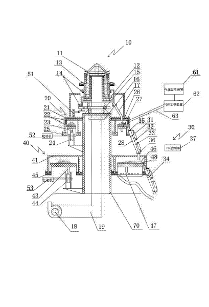
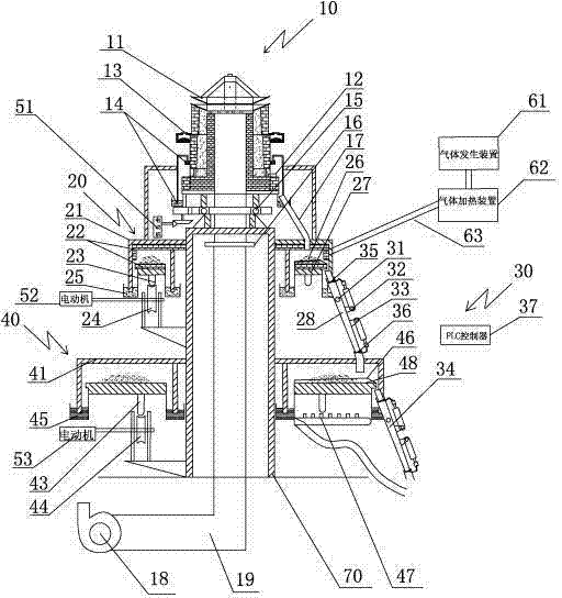
[0019] An energy-saving and environment-friendly reduction converter, which includes a furnace body (10), a reduction device (20), a cooling device (40), a gas generating device (61), a gas heating device (62) and a support (70), the furnace body (10 ) includes a fan (18) and an air duct (19), the furnace body (10), the reducing device (20) and the cooling device (40) are vertically arranged up and down on the same axis; the furnace body (10) is installed on the rotary table (15 ), the motor I (51) drives the rotary table (15) to rotate, and a sealing ring (16) is provided on the air channel (19) below the rotary table (15); the reduction device (20) is: a reduction disk ( 27) is provided with an iron cover I (21), and the iron cover I (21) is fixedly connected with the support (70). The edge of the reduction disk (27) is provided with a sand seal II (25), and the sand seal II (25) is connected with The restoration disk (27) is fixedly connected, and the ball I (23) is arrange...


PUM


Abstract

The invention relates to an energy-saving environmentally-friendly reduction converter. The converter comprises a converter body, a reduction device, a cooling device, an air generation device, an air heating device and a bracket, wherein the converter body comprises a fan and an air flue; the converter body, the reduction device and the cooling device are vertically arranged from top to bottom on the same axis; a motor I drives a rotary platform to enable the converter body to rotate; a motor II and a motor III respectively drive a reduction disk and a cooling disk to rotate, so that reduction and cooling speeds are high, and reduction and cooling efficiencies are high; and a sand seal, a liquid seal and a fire-resistant heat insulation layer are adopted, thereby reducing heat loss and greatly saving energy.

Description

technical field [0001] The invention relates to a production equipment for reducing sponge iron, in particular to an energy-saving and environment-friendly reducing converter. Background technique [0002] At present, the production equipment of sponge iron has problems such as long reduction time, insufficient reduction, and strict requirements on raw materials and fuels. The traditional tunnel kiln enters in one direction and exits in one direction. There is a preheating section in the front, a heating and reducing section in the middle, and a cooling section at the end; the heat in the cooling section is wasted, a lot of energy is wasted, the cooling speed is slow, and the production efficiency is low. . Moreover, during the heating and reduction process of sponge iron, because of the volume expansion of sponge iron, the production is stagnated and the production output is greatly reduced; the use of coal-fired heating not only takes a long time for reduction, but also c...

Claims


Application Information

Patent Timeline
Patent Type & Authority Applications(China)
IPC IPC(8): C21B13/08
Inventor 周广砥
Owner 周广砥
Why Eureka
Try Eureka