
Method for controlling and reducing thermal load of internal combustion engine

A technology for internal combustion engines, thermal loads, applied in the direction of internal combustion piston engines, combustion engines, cooling of engines, etc.

Inactive Publication Date: 2012-03-21
FORD GLOBAL TECH LLC
View PDF6 Cites 2 Cited by
  • Summary
  • Abstract
  • Description
  • Claims
  • Application Information

AI Technical Summary

Problems solved by technology

[0027] From the above description it is clear that modern internal combustion engines are equipped with multiple heat exchangers which without exception have to be formed with a sufficiently large heat transfer surface in order to perform their function, which is usually in the A problem in the dimensioning and setting of the individual heat exchangers in the front area, which leads to inconsistencies

Method used


Image

  • Method for controlling and reducing thermal load of internal combustion engine
  • Method for controlling and reducing thermal load of internal combustion engine

Examples


Embodiment Construction

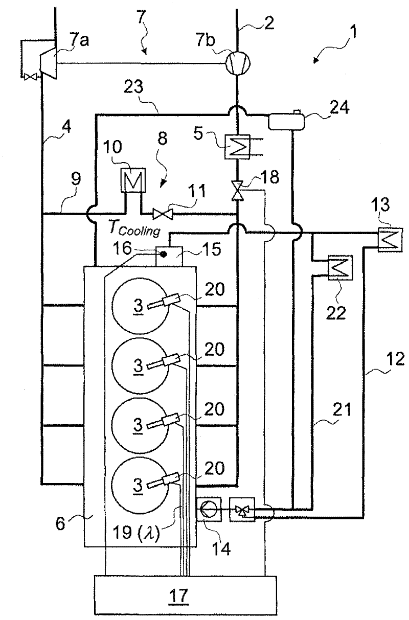
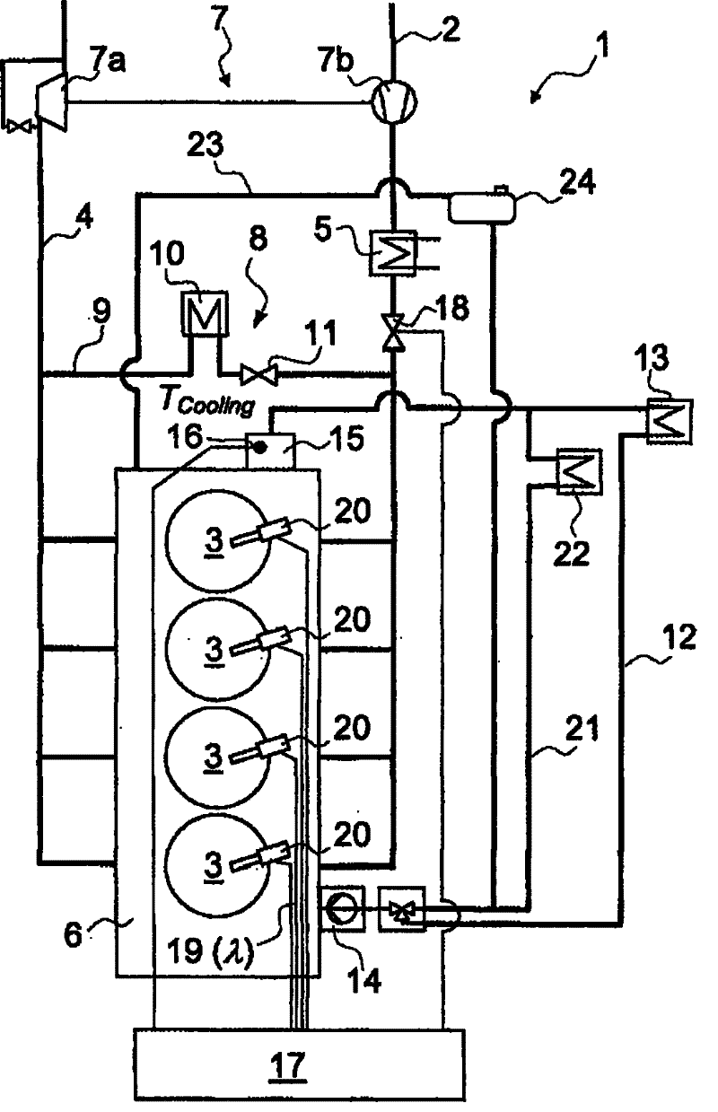
[0125] figure 1 A first embodiment of an internal combustion engine 1 implementing a method of limiting thermal load is schematically shown.

[0126] The internal combustion engine is a direct-injected four-cylinder in-line engine 1 , in which four cylinders 3 are arranged along the longitudinal axis of the cylinder head 6 , ie arranged in-line, and are equipped in each case with injectors 20 for injecting fuel. The injectors 20 are independently actuated, ie controlled, by the engine controller 17 via the control line 19 . The injected fuel quantity is used to set the air ratio λ.

[0127] The exhaust line 4 is used to expel hot combustion gases, and the intake line 2 is used to supply fresh air or a fresh mixture to the cylinder 3 . In order to adjust the load, a throttle valve 18 is provided in the intake line 2 as a closing element, which throttle valve 18 can likewise be controlled and / or adjusted by the engine controller 17 .

[0128] For charging purposes, the intern...


PUM


Abstract

The method involves making chemical pulp to react with chlorine dioxide at a temperature of 50 to 150 degree Celsius and a pH in the range from 2 to 7, until more than 90 percent of the chlorine dioxide is reacted. Aqueous mixture is made to react without separating off constituents of the mixture with 0.1 to 5 percent by weight of hydrogen peroxide in the presence of molybdate in an amount of 10 to 2000 ppm of molybdenum or tungstate in an amount of 200 to 10000 ppm of tungsten, at the temperature of 50 to 150 degree Celsius. The respective amounts are based on used mass of dry chemical pulp. Aqueous solution is brought into contact with water-insoluble, cationized inorganic support material, where cationized phyllosilicate or bentonite ion-exchanged with a quaternary ammonium salt is used as the material.

Description

technical field [0001] The invention relates to a method for limiting and reducing the thermal load of an internal combustion engine having at least one cylinder head and having at least one cylinder. [0002] The invention also relates to an internal combustion engine implementing such a method. Background technique [0003] Internal combustion engines of the type described above are used in drive units for motor vehicles. In the context of the present invention, the expression "internal combustion engine" encompasses diesel engines and spark ignition engines, and also hybrid internal combustion engines, ie internal combustion engines which operate using a hybrid combustion process. [0004] An internal combustion engine has at least one cylinder head to form at least one cylinder (ie combustion chamber), said cylinder head being connected to a cylinder block. During the charge exchange, combustion gases are expelled via the outlet and the combustion chamber is charged, i...

Claims


Application Information

Patent Timeline
IPC IPC(8): F02D41/02F01P11/16
CPCF02B29/0406F01P2060/08Y02T10/40F02D2200/021F02D41/0055F02M25/0713F01P2025/33F02M25/0707F02M25/0727F02D41/22F02D41/1475F02M26/05F02M26/10F02M26/23
Inventor A・布罗伊尔J・梅林
Owner FORD GLOBAL TECH LLC
Learn More