Transmission of power bidirectionally and without contact to charge electric vehicles

A vehicle, electric drive technology, used in electric vehicle charging technology, electric vehicles, charging stations, etc., can solve problems such as increased contact resistance, easy contamination of the plug system, and danger of overheating.

Inactive Publication Date: 2012-03-21
SIEMENS AG
View PDF4 Cites 12 Cited by
  • Summary
  • Abstract
  • Description
  • Claims
  • Application Information

AI Technical Summary

Problems solved by technology

In addition, the plug system is prone to contamination and there is a corre...

Method used


Image

  • Transmission of power bidirectionally and without contact to charge electric vehicles
  • Transmission of power bidirectionally and without contact to charge electric vehicles
  • Transmission of power bidirectionally and without contact to charge electric vehicles

Examples


Embodiment Construction

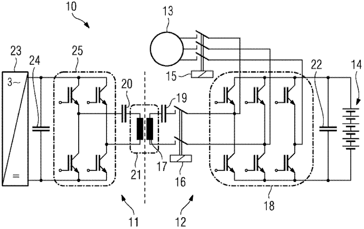
[0021] figure 1 A first overall system 10 is shown, which consists of a vehicle-side element 12 and a fixed element 11 and comprises a first embodiment of the invention. The fixed element 11 is located outside the vehicle, for example underneath the vehicle when the vehicle is at the charging station.

[0022] The vehicle-side element 12 comprises an electric motor 13 for driving the vehicle, a battery 14 , an inverter 18 , an intermediate circuit capacitor 22 , a first switching device 15 , a second switching device 16 , a coil as part of the vehicle-side of the transmitter 21 Device 17 and resonant capacitor 19 on the vehicle side.

[0023] The stationary component 11 comprises a rectifier 23 , a stationary-side intermediate circuit capacitor 24 and a stationary-side converter 25 . Furthermore, the fixed element 11 includes a fixed-side resonant capacitor 20 and a fixed-side part of a transmitter 21 .

[0024] To charge the vehicle's battery 14, the rectifier 23 converts ...


PUM


Abstract

The invention relates to a device for transmitting power without contact to charge electric vehicles. The converter that feeds the electric drive and is present anyway in an electric vehicle also is used for transmitting energy to the vehicle without contact. For this purpose, a resonant operation is proposed for the inductive transmission of energy. The leakage inductance of the transformer is resonantly adjusted therefor by means of a serial capacitor. The load current is then switched at the zero-crossing.

Description

technical field [0001] The invention relates to bi-directional and contactless transfer of power for charging electric vehicles. Background technique [0002] Electric vehicles are usually connected to the grid or to a stationary charging rectifier via plug connectors. If a 20 kWh battery is to be charged within 15 minutes (so-called 6C charging), a charging power of approximately 87 kW is to be expected, which corresponds to a current of 125 A in a 400-volt grid. This corresponds to the largest commercially available plug having a diameter of 126mm and a length of 282mm. The manual force required for insertion or extraction is hundreds of Newtons, which makes it difficult to operate. Higher charging powers are not possible to transmit with currently available plug systems. Furthermore, the plug system is prone to contamination and there is a corresponding risk of overheating due to the increased contact resistance due to corrosion. An alternative that circumvents this p...

Claims


Application Information

Patent Timeline
IPC IPC(8): B60L11/18H02J5/00
CPCY02T90/14B60L11/1814B60L11/182Y02T90/127Y02T10/7088B60L11/1812B60L11/1803Y02T10/7005H02J5/005B60L15/007Y02T90/122Y02T10/7072Y04S10/126B60L53/22B60L50/51B60L53/24B60L55/00H02J7/00712H02J2207/20B60L53/122Y02E60/00Y02T10/64Y02T10/70H02J50/12Y02T90/12Y02T90/16
Inventor R.柯德斯G.格里彭特罗格T.科马S.尼尔伯克
Owner SIEMENS AG
Why Eureka
Try Eureka