Template-free energy consumption steel plate shear wall and construction method thereof

A steel plate shear wall, no formwork technology, applied in the direction of walls, building components, earthquake resistance, etc., can solve the problems of poor energy consumption performance, difficult construction, labor and time-consuming supporting formwork, etc., to enhance fire performance and reduce connection welding. Process, the effect of improving ability

Inactive Publication Date: 2012-04-04
姚攀峰
View PDF13 Cites 19 Cited by
  • Summary
  • Abstract
  • Description
  • Claims
  • Application Information

AI Technical Summary

Problems solved by technology

[0003] The purpose of the present invention is to provide a formwork-free energy-consuming steel plate shear wall and its construction method, to solve the difficulty in construction of the e

Method used


Image

  • Template-free energy consumption steel plate shear wall and construction method thereof
  • Template-free energy consumption steel plate shear wall and construction method thereof
  • Template-free energy consumption steel plate shear wall and construction method thereof

Examples


Embodiment 1

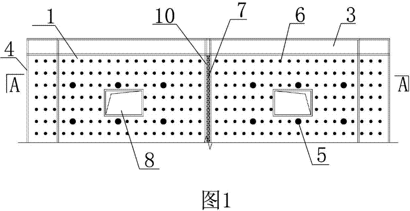
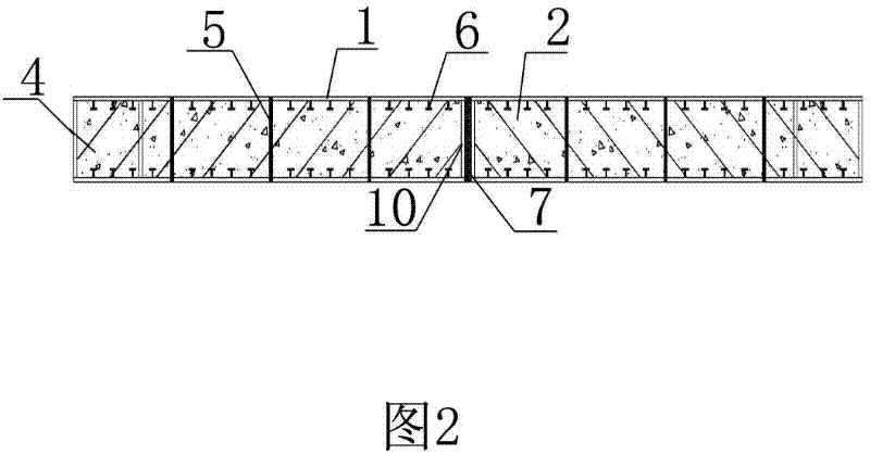
[0042] Embodiment one sees figure 1 and figure 2 As shown, a formwork-free energy-dissipating steel plate shear wall structure is composed of outer edge members and a body. The outer edge members include horizontal members 3 on the top and bottom of the body and vertical members 4 on the side of the body. The horizontal member 3 and the vertical member 4 are welded or bolted to the main body. The main body is composed of an inner core 2 and an outer cladding steel plate 1. The inner core 2 is sandwiched between mutually parallel outer cladding steel plates 1. The steel plates are tied by tension bolts 5, and vertical seams are reserved between the outsourcing steel plates 1 in the same plane, and the outsourcing steel plates are blocked by the sealing steel plates 10 at the vertical seams, and the power consumption is installed in the vertical seams. Part 7 can be connected. The vertical member 4 is a vertical plate or a column. The horizontal member 3 is a transverse stee...

Embodiment 2

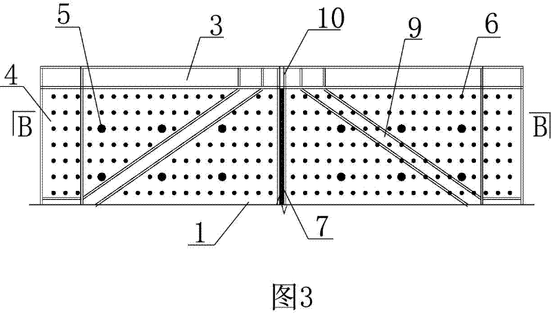
[0043] Embodiment two see image 3 and Figure 4 As shown, the difference from Embodiment 1 is that there is no opening on the body, and oblique stiffeners 9 are provided on the outer surface of the outer cladding steel plate.

Embodiment 3

[0044] Embodiment three see Figure 5 ~ Figure 7 As shown, the difference from the second embodiment is that there is no opening on the body, and the outer surface of the outer cladding steel plate is not provided with oblique stiffeners.

[0045] The specific implementation of the energy dissipation connector 7 can be found in Figure 8 to Figure 16 , Figure 8 The energy-dissipating connector 7 mentioned above is an energy-dissipating block 7.1 formed of filling material. Figure 9 The energy-dissipating connector 7 described in the above is an energy-dissipating block 7.1 formed of filling material, and the plugging steel plate 10 is welded with a stud B13. Figure 10 The energy-dissipating connecting piece 7 described in the above is an energy-dissipating block 7.1 formed of filling material, and a steel bar 15 is welded on the sealing steel plate 10 . The above-mentioned filling material is concrete, cement mortar, gypsum, lime or rubber, and fibers, steel bars or stee...


PUM

PropertyMeasurementUnit
Widthaaaaaaaaaa

Abstract

The invention relates to a template-free energy consumption steel plate shear wall and a construction method thereof, which belong to the technical field of building components. A shear wall body consists of a concrete inner core and outer covering steel plates, wherein the concrete inner core is clamped between the two mutually parallel outer covering steel plates, the mutually parallel outer covering steel plates are in tension connection through opposite-pull screw bolts, a vertical seam is preserved between the outer covering steel plates in the same plane, the outer covering steel plates are sealed and plugged at the vertical seam part through sealing and plugging steel plates, and energy consumption connecting elements are arranged in the vertical seams. The template-free energy consumption steel plate shear wall has the advantages that the shock resistance performance is good, the construction is convenient, the mechanical property of two kinds of major building materials of concrete and steel can be fully exerted, and the like. The template-free energy consumption steel plate shear wall can be widely applied to the shear wall structure of multi-storey or tall buildings and the construction of the shear wall structure.

Description

technical field [0001] The invention relates to a structural wall and a construction method thereof, in particular to a steel plate shear wall and a construction method thereof. Background technique [0002] The steel plate shear wall has extremely high lateral force resistance, good ductility, excellent energy dissipation capacity and high safety reserve, and has become a new structural form of multi-story steel structures. The existing practice is generally internal It is a steel plate, and the outside is wrapped with reinforced concrete. This method has the following problems: 1. Construction is difficult, and the construction of this hybrid structure is difficult; 2. When an earthquake occurs, the energy consumption capacity is poor; 3. The reinforced concrete outsourced is easy to crack or damage and the maintenance cost is high; 4. The connection of components is difficult. Contents of the invention [0003] The purpose of the present invention is to provide a for...

Claims


Application Information

Patent Timeline
IPC IPC(8): E04B2/86E04B1/98E04G21/00
Inventor 姚攀峰
Owner 姚攀峰
Why Eureka
Try Eureka