Heat sink with needle rib-recessed composite array and method for arranging needle rib-recessed composite array

A composite array and pin-fin technology, applied in the field of heat dissipation devices, can solve the problems of increased power consumption and noise of pumps or fans, large flow resistance of cooling fluid, increased flow loss, etc., to reduce weight, reduce power consumption, and reduce density Effect

Inactive Publication Date: 2012-04-11
SHANGHAI JIAO TONG UNIV
View PDF4 Cites 3 Cited by
  • Summary
  • Abstract
  • Description
  • Claims
  • Application Information

AI Technical Summary

Problems solved by technology

[0004]Conventional pin-fin heat sinks also have their limitations, that is, while providing high heat transfer performance, they cause a large flow resistance of the cooling fluid, especially at high flow rates even more so under the condition
When the flow rate is large, the flow will be separated from the surface of the pin fins prematurely, and a large area of ​​highly turbulent wake will be generated on the back of each pin fin, which will cause the flow loss in the flow channel to increase rapidly, and cause pump or fan work in the system. rapid increase in power consumption and noise

Method used


Image

  • Heat sink with needle rib-recessed composite array and method for arranging needle rib-recessed composite array
  • Heat sink with needle rib-recessed composite array and method for arranging needle rib-recessed composite array
  • Heat sink with needle rib-recessed composite array and method for arranging needle rib-recessed composite array

Examples


specific Embodiment 1

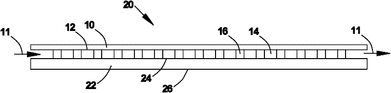
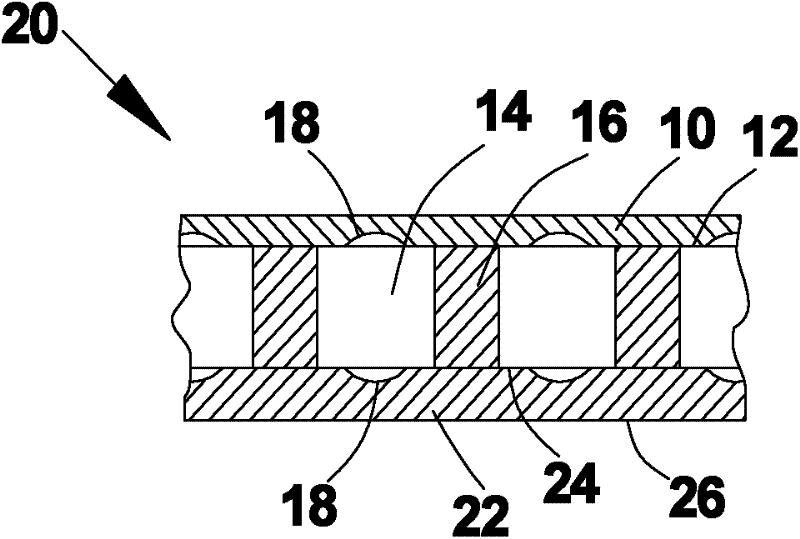
[0035] Such as figure 1 As shown, the pin fin-recess composite array heat sink 20 in this embodiment includes: a base plate 22 , a plurality of pin fins 16 , cooling channels 14 and a top plate 10 . The wall surface 26 of the substrate 22 of the heat sink is in close contact with the surface of the heat-generating device, so as to receive heat from the surface of the device. This heat is then carried away by the cooling fluid in the cooling channels 14 . The base plate 22 and the top plate 10 can be coupled together through the holes 23 by fasteners.

[0036] The pin fins 16 are formed on the inner wall surface 24 of the substrate by integral milling or brazing or casting or other processing methods. Both the pin fins 16 and the substrate 22 are made of high thermal conductivity materials, such as copper, aluminum or AlSiC. The pin rib 16 has a columnar shape with a circular cross section. Of course, the pin fins in the present invention can also be configured to have a rh...

specific Embodiment 2

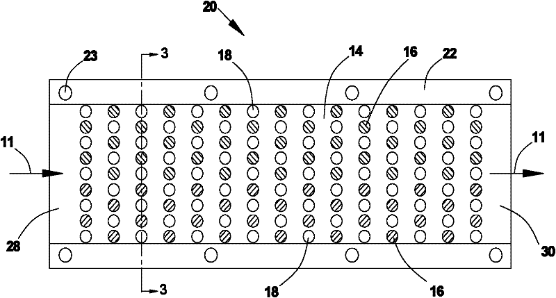
[0039] Figure 4 and Figure 5 Shown is a fin-and-dimple array heat sink 20 having another arrangement. and figure 2 The difference between the shown pin fin-depression array heat sink is that the depression 18 is not only arranged on the inner wall surface 24 of the substrate at the minimum flow section between the transverse pin fins 16, but also between every two columns of pin fins 16 in the longitudinal direction. There is a column of depressions 18 . The recesses 18 are staggeredly arranged on the inner wall surface 24 of the substrate. and figure 2 Compared with the pin fin-recess array arrangement scheme shown, Figure 4 In the shown arrangement the base plate inner wall 24 has more depressions. Such as Figure 6 As shown, when the fluid flows through the array of pin fins 16 and depressions 18, strong eddy currents 15 are generated, and the interaction between the eddy currents can significantly further enhance the turbulent flow mixing near the inner wall su...

specific Embodiment 3

[0041] Figure 7 It is described that the fin-depression array heat sink 20 simultaneously dissipates heat from two devices. In this embodiment, the cooling channel 14 is bounded between the upper and lower base plates 22 . The inner wall surfaces 24 of the two substrates are processed with pin ribs 16 and recesses 18 . The pin rib 16 is connected to the upper and lower base plates 22 . In this arrangement, therefore, there is no top plate 10 . exist Figure 7 In the illustrated embodiment, the configuration scheme of pin fins and depressions in the cooling channel 14 between the two base plates 22 is the same as that of figure 2 or Figure 4 Similar to what is shown. The cooling fluid flows into the heat sink to convectively cool the upper and lower substrates 22 . Obviously, such a heat dissipation solution is very compact, which is beneficial to saving space, weight and cost, and is very beneficial to the cooling design of aviation and aerospace electronic equipment...


PUM


Abstract

The invention discloses a heat sink with a needle rib-recessed composite array structure. The heat sink comprises a cooling channel, a plurality of needle ribs, a plurality of recesses, a substrate and a top plate, wherein the substrate and the top plate are provided with opposite inner wall surfaces respectively; the cooling channel is defined between the two inner wall surfaces; the inner wall surface of the substrate is provided with a plurality of needle ribs to form needle rib arrays; the needle rib arrays are arranged in a staggered mode; on either the substrate or the top plate, at least the inner wall surface of the substrate is provided with a plurality of recesses to form recess arrays; in the cooling channel, a minimum flowing cross section is formed between the needle ribs in a transverse direction, a recess is formed on at least one minimum flowing cross section, and the plurality of recesses are arranged in a staggered mode in a longitudinal direction to form the recess arrays; and the needle rib arrays and the recess arrays form the needle rib-recessed composite array structure. The invention also discloses a method for arranging the heat sink. Compared with the conventional needle rib array heat sink, the heat sink has higher heat transfer performance and the same or even lower flow resistance; therefore, the heat sink has higher comprehensive thermal performance.

Description

technical field [0001] The invention relates to a heat dissipation device, in particular to a heat dissipation device (or heat sink) having a compound array structure of pin fins and depressions. The present invention also relates to a method for arranging the pin fin-depression composite array for the aforementioned heat sink. Background technique [0002] In modern industry, there are many devices or devices that emit a lot of heat during work, and high-efficiency heat dissipation devices (heat sinks) are required to dissipate the heat in time to maintain normal operation, normal life, and ensure reliability. These heating devices that need to be cooled include high-power integrated circuits, central processing units (CPUs), high-power semiconductor lasers, etc. in the electronics industry, as well as reactors in chemical and pharmaceutical processes. On the other hand, the above-mentioned heat-generating devices are developing in the direction of high power and miniaturi...

Claims


Application Information

Patent Timeline
Patent Type & Authority Applications(China)
IPC IPC(8): F25D9/00H05K7/20
Inventor 饶宇许亚敏
Owner SHANGHAI JIAO TONG UNIV
Why Eureka
Try Eureka