Array attenuator for high-energy laser and manufacturing method thereof

A high-energy laser and attenuator technology, used in photometry, instruments, scientific instruments, etc., can solve problems such as limited application range, large differences in absorption coefficients, difficult parameter measurement, etc., to ensure installation accuracy, ensure consistency, The effect of improving the reflectivity of the surface

Active Publication Date: 2012-04-11
NORTHWEST INST OF NUCLEAR TECH
View PDF2 Cites 9 Cited by
  • Summary
  • Abstract
  • Description
  • Claims
  • Application Information

AI Technical Summary

Problems solved by technology

The problem with this kind of attenuator is that the graphite material itself has a high absorption rate of the incident laser light in the sampling attenuation, and it is generally used for the laser power of 10 -5 times high multiplier attenuation, difficult to use for 10 -3 In addition, this attenuator is difficult to measure the parameters when the strong laser is obliquely incident. When the laser enters the laser incident hole at a certain angle, the hole wall of the graphite material has a greater absorption of the laser light. High, and corresponding to different incident angles, the absorption coefficient of the hole wall to the incident laser is quite different, so it is difficult to use the laser light intensity attenuation and parameter measurement at oblique incidence, which limits the application range of this method

Method used


Image

  • Array attenuator for high-energy laser and manufacturing method thereof
  • Array attenuator for high-energy laser and manufacturing method thereof
  • Array attenuator for high-energy laser and manufacturing method thereof

Examples


Embodiment Construction

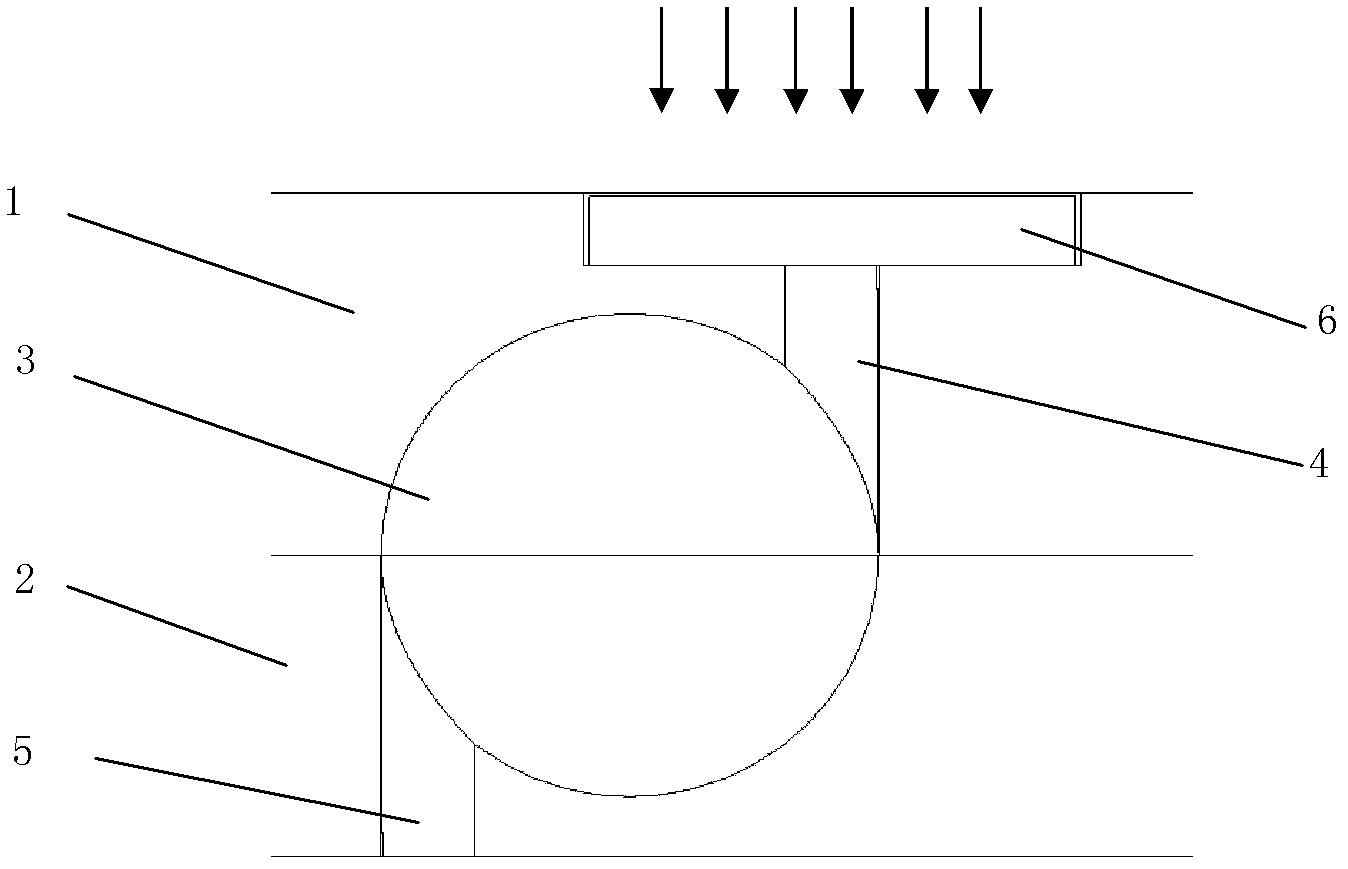
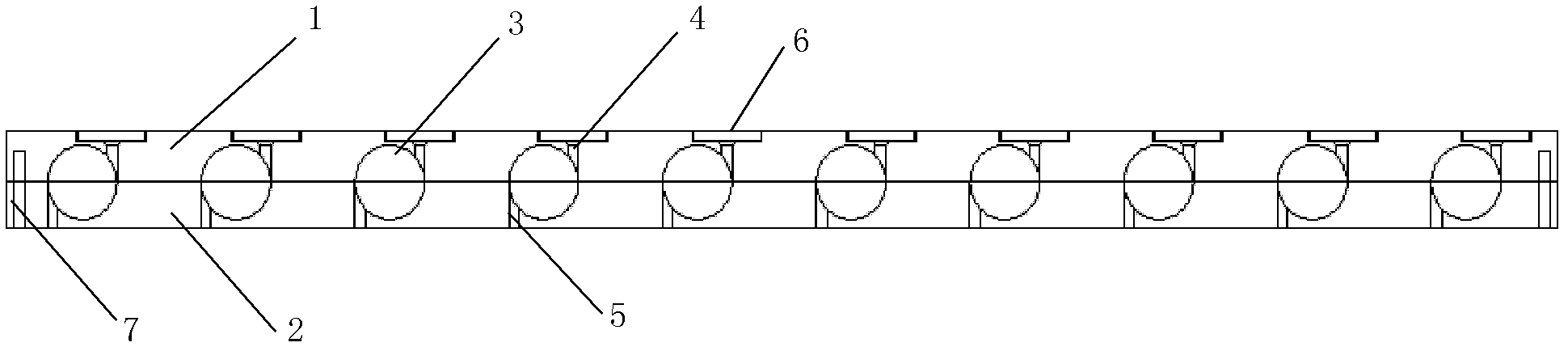
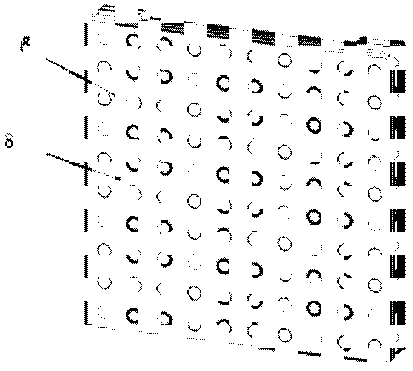
[0030] Such as figure 1 As shown, hemispherical cavities and laser coupling holes with equal diameters are respectively processed on the metal front panel 1 and rear panel 2, and the two panels are stacked together so that the corresponding hemispherical cavities are buckled together to form an integrating sphere The inner cavity 3 and two laser coupling holes are respectively located on opposite sides of the spherical cavity, tangent to the maximum diameter of the hemispherical cavity, forming a laser entrance hole 4 and a laser exit hole 5 . Laser along the test figure 1 The direction of the arrow in the middle is coupled into the cavity 3 of the integrating sphere from the laser entrance hole 4 through the optical window 6. After repeated absorption and reflection in the cavity, only a small part of the light is finally emitted from the laser exit hole 5, realizing the control of strong laser power. Density attenuation. Such as figure 2 As shown, if there are multiple i...


PUM


Abstract

The invention relates to an array attenuator for a high-energy laser and a manufacturing method thereof. The array attenuator comprises a front panel, a rear panel and an array of a plurality of integrating sphere cavities, wherein the front panel and the rear panel are arranged along an incident direction of the laser; each of the integrating sphere cavities is formed by two hemispherical cavities in spliced connection; a laser incident hole and a laser emergent hole are formed on an edge of each of the integrating sphere cavities; the front panel and the rear panel are made of metallic materials; and a diffuse transmission optical window is mounted at the laser incident hole. Compared with the graphite in same size, the array attenuator provided by the invention is low in absorption rate for laser power, thereby being suitable for the attenuation of a medium multiple laser power density. Meanwhile, the diffuse transmission optical window is mounted in front of the laser incident hole, so that the laser passing by the optical window is multi-angularly coupled in the laser incident hole, thereby keeping a basic invariable attenuation coefficient of the attenuator when the laser obliquely incomes within a certain angle scope.

Description

technical field [0001] The invention relates to a high-energy laser array attenuator and its manufacturing method, in particular to a high-energy laser metal array attenuator and its manufacturing method. Background technique [0002] In the measurement of high-energy laser parameters, the photodetector array sampling method is often used to obtain the temporal and spatial distribution information of laser spot power density. Since the laser power density at the test position is generally high, it is difficult to directly use the photodetector array to measure, so in the actual test, the measured laser power density needs to be reasonably attenuated to meet the range of the photodetector. scope. The ideal optical attenuation method should be independent of the wavelength, incident angle and polarization state of the incident laser, and only attenuate the amplitude of the incident laser accordingly, and the attenuation is linear within a certain range. [0003] At present, ...

Claims


Application Information

Patent Timeline
Patent Type & Authority Applications(China)
IPC IPC(8): G01J1/04
Inventor 王振宝杨鹏翎冯国斌冯刚张磊闫燕陈绍武
Owner NORTHWEST INST OF NUCLEAR TECH
Why Eureka
Try Eureka