Air guiding heat dissipation device for computer

A technology of heat dissipation device and air guide device, which is applied in computing, instrumentation, electrical and digital data processing, etc., can solve the problems of temperature rise, unavoidable noise, affecting heat dissipation effect, etc., and achieve the effect of reducing heat dissipation efficiency.

Inactive Publication Date: 2012-04-18
周志农
View PDF4 Cites 10 Cited by
  • Summary
  • Abstract
  • Description
  • Claims
  • Application Information

AI Technical Summary

Problems solved by technology

If the rotating speed of the power supply fan 101 is greatly reduced in order to reduce noise, the heat emitted from the CPU and the graphics card cannot be discharged out of the chassis quickly, and the heat remaining in the chassis will cause the overall temperature inside the chassis to rise, resulting in heat dissipation for the CPU and the graphics card. Increased airflow temperature reduces cooling efficiency
[0004] Under the existing technology, even in the case of low configuration, the speed of the power supply fan cannot be reduced to the point where no noise can be heard
When the computer configuration is high and it is running under high load, in order to let the heat out of the chassis as soon as possible, it is necessary to add an auxiliary chassis fan and increase the fan speed to meet the heat dissipation requirements, and the noise is inevitable.
In addition, long-term excessive airflow will bring more dust into the chassis, causing the heat sink to be blocked by dust, further affecting the heat dissipation effect
If the computer does not have a front auxiliary fan and is placed under a closed desk at the back, the hot air cannot be discharged normally because the rear air intake and exhaust vent are too close, and in severe cases, the computer will overheat and shut down

Method used


Image

  • Air guiding heat dissipation device for computer
  • Air guiding heat dissipation device for computer
  • Air guiding heat dissipation device for computer

Examples


Embodiment 1

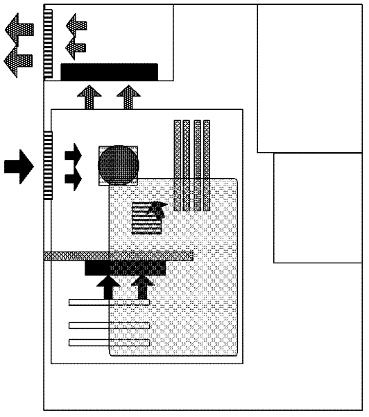
[0035] figure 2 , image 3 It is a schematic diagram of plane and three-dimensional structure of a general performance computer installed with the air guide and heat dissipation device of the present invention. The machine is a general-purpose ATX vertical structure, equipped with a dual-core CPU with a maximum power consumption of 65W, and an integrated graphics card. The chassis power supply is an active high-efficiency power supply with a rated power of 200W and a 120mm-caliber fan. A fan, a radiator with a heat pipe is used on the CPU. The port of the large-diameter area of ​​the air-guiding heat-dissipating device is closely attached to the air inlet of the power supply of the chassis, the CPU heat sink is embedded in the port of the small-diameter area of ​​the air-guiding heat-dissipating device, and the end mask of the small-diameter area of ​​the air-guiding heat-dissipating device is above the north bridge radiator of the main board. Pull out the fan wire from the...

Embodiment 2

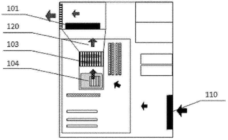
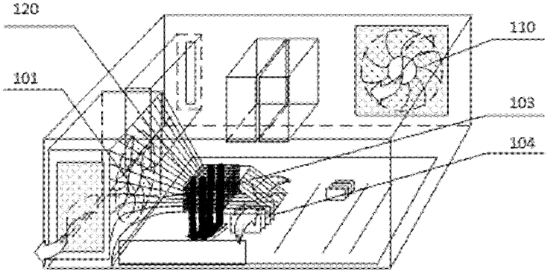
[0040] Figure 4 , Figure 5 It is a schematic diagram of plane and three-dimensional structure of a high-performance computer installed with the air guide and heat dissipation device of the present invention. The machine is a general-purpose ATX vertical structure, equipped with a 4-core CPU with a maximum power consumption of 95W and a high-end graphics card with a maximum power consumption of 125W. The power supply of the chassis is an active high-efficiency power supply with a rated power There is a 120mm caliber graphics card cooling fan. Install a radiator with heat pipes and corresponding air guide cooling devices on the CPU and graphics card. Pull out the fan wire from the power box of the chassis and connect it to the fan reducer together with the graphics card cooling fan wire.

[0041] Heat dissipation process: (1) Upper part: cold air enters the case from the air inlet 110 on the front panel, passes through the north bridge radiator 104 of the motherboard, enters th...

Embodiment 3

[0044] Figure 6 , Figure 7 Schematic diagram of the plane and three-dimensional structure of an ultra-high-performance computer installed with the air guide and heat dissipation device of the present invention:

[0045] The chassis is a general-purpose ATX vertical structure, equipped with a 6-core CPU with a maximum power consumption of 125W and a top-level graphics card with a maximum power consumption of 250W. The chassis power supply is an active high-efficiency power supply with a rated power of 500W and a 120mm diameter fan. The air inlet of this machine is on the side panel and the rear baffle, and the radiator with heat pipe and the corresponding air guide and heat dissipation device are installed on the CPU and the graphics card. Because the graphics card generates a lot of heat under high load, an air guide cooling device with two 120mm diameter fans is installed, and the fan wires are pulled out from the power supply box and connected to the fan reducer together ...


PUM


Abstract

The invention relates to an air guiding heat dissipation device for a computer; the air guiding heat dissipation device is characterized in that the air guiding heat dissipation device is an air guiding pipe which is provided with a tapered ventilating duct and is arranged in the computer; the tapered ventilating duct is arranged in the middle of the air guiding heat dissipation device; a large caliber area and a small caliber area are respectively arranged at two ends of the tapered ventilating duct; a cooling fan is arranged in the large caliber area of the air guiding heat dissipation device; and a heating chip or a cooling fin on a radiator of the heating chip are arranged at the outer side of a port of the smaller caliber area of the air guiding device or embedded in the smaller caliber area. As the air guiding device has the bottleneck effect, wind speed larger than that of the lager caliber area is formed in gaps of the cooling fin in the smaller caliber area of the air guiding device when the fan in the large caliber area is started; and compared with the prior art that the fan is attached on the cooling fin, the air guiding heat dissipation device greatly increases the heat dissipation efficiency. The computer adopting the air guiding heat dissipation device has the advantages of low cost, light weight and achieved ultra-low-noise effect in case of high configuration and high load.

Description

technical field [0001] The invention relates to the field of computer heat dissipation, in particular to a computer air guide and heat dissipation device. Background technique [0002] The power supply fan on the computer, the fan on the CPU heat sink and the fan on the graphics card heat sink usually all make certain noises, and the heat dissipation method under the prior art is usually that the fan is directly attached to the heat sink of the heat sink to blow hot air into the chassis, and then use The power supply fan and chassis auxiliary fan draw hot air out of the chassis. In this way, no matter how you reduce the noise of the fan on the heat sink, the noise from the power supply fan and the chassis auxiliary fan still exists. The mute effect of the computer under the prior art can usually only be achieved at a low load, and the noise is still obvious when used in a very quiet environment. [0003] figure 1 It is a schematic diagram of the plane structure of an ordi...

Claims


Application Information

Patent Timeline
Patent Type & Authority Applications(China)
IPC IPC(8): G06F1/20
Inventor 周志农
Owner 周志农
Why Eureka
Try Eureka