
Vibrato-drilling type punching drilling rig

A vibration mechanism and drilling rig technology, applied in mechanically driven excavators/dredgers, vibration generating devices, earth movers/shovels, etc., can solve the problem of increasing construction costs, high center of gravity of drilling rigs, affecting work efficiency and project progress and other problems, to achieve the effect of reducing equipment cost, convenient moving and transportation, and reducing the height of the mast

Active Publication Date: 2014-05-14
HENR TECH GUANGXI CO LTD
View PDF11 Cites 0 Cited by
  • Summary
  • Abstract
  • Description
  • Claims
  • Application Information

AI Technical Summary

Problems solved by technology

For example: 1. The torque requirement of the power head is very high, especially when drilling large diameter holes; 2. The drill pipe must bear a large torque during operation, resulting in reduced reliability; 3. Limited by the length of the retractable drill pipe, the drilling depth Limited; 4. The mast and drill pipe must have a certain height and weight, which makes the drilling rig have the disadvantages of high center of gravity and poor moving stability
5. When moving and transporting, it is necessary to disassemble the mast and other related components, and then assemble them at the new construction site, which is time-consuming, affects work efficiency and project progress, and the cost of the transition is high, which increases the construction cost accordingly; 6. Only the circle can be drilled Shaped pile hole
7. Due to the complex structure of the power head and the retractable drill pipe, the price of the rotary drilling rig is expensive and the one-time investment is large
[0005] The current underground diaphragm wall grab equipment on the market mainly relies on the gravity of the grab mechanism to enter the soil layer, so the grab mechanism itself is very heavy, the whole machine is huge and requires high power, and the price is expensive.

Method used


Image

  • Vibrato-drilling type punching drilling rig
  • Vibrato-drilling type punching drilling rig
  • Vibrato-drilling type punching drilling rig

Examples


Embodiment Construction

[0024] Below in conjunction with accompanying drawing, the present invention will be further described:

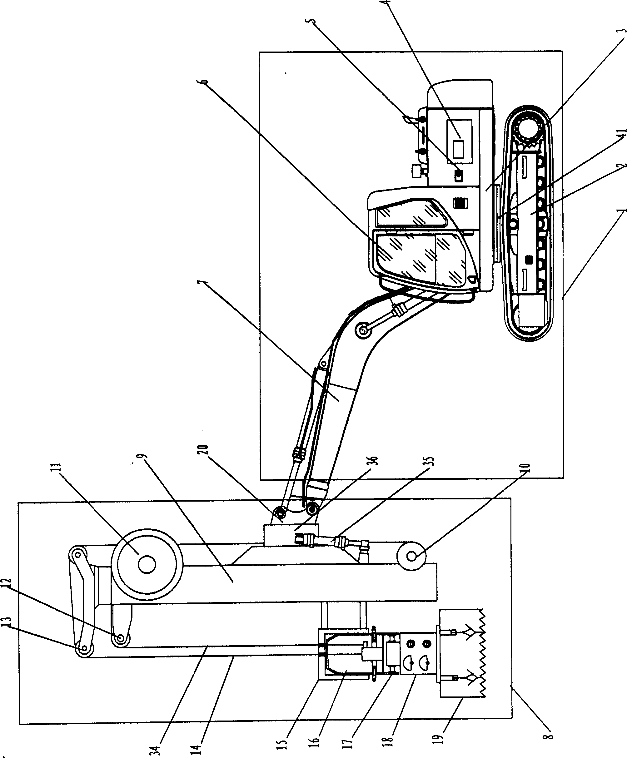
[0025] Such as Figure 1 and Figure II As shown, the vibratory drilling rig of the present invention is composed of a chassis mechanism 1 and a working device 8; The cab 6, the engine 4, the hydraulic system 5 and the boom 7 controlled by the hydraulic system 5 are composed. Chassis mechanism 1 also can adopt crawler or wheel type hydraulic excavator.

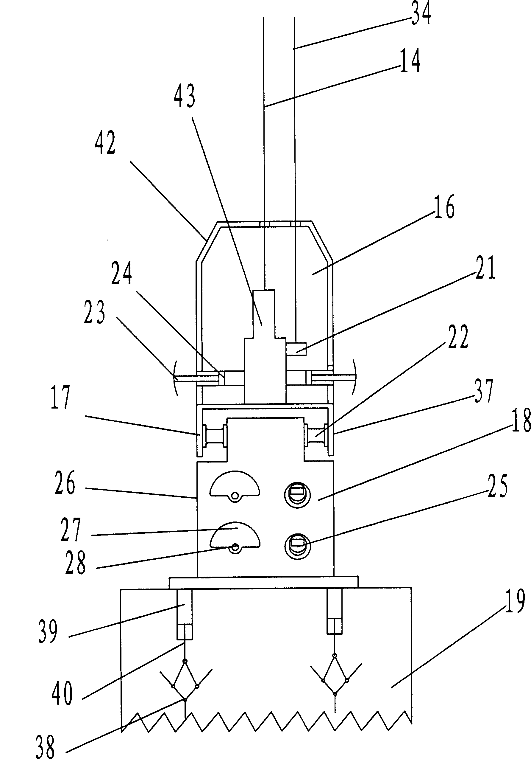
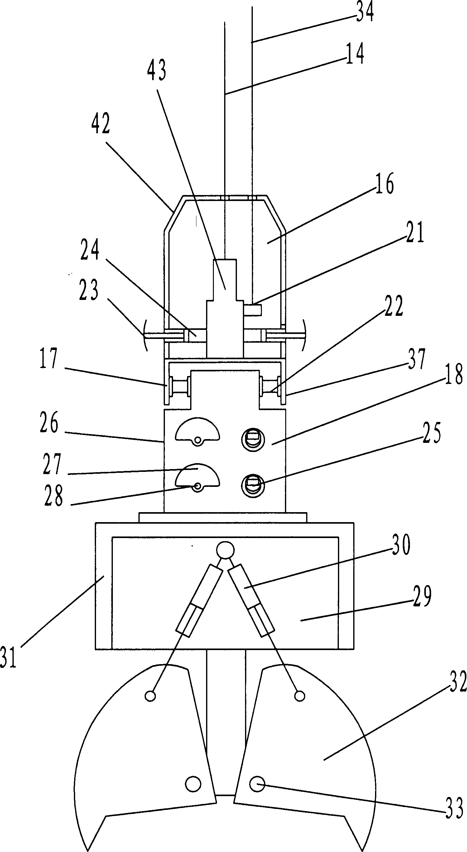
[0026] Working device 8 is mainly made of mast mechanism 9, vibrating mechanism 18, damping mechanism 17, guiding mechanism 16 and earth-borrowing bucket 19, and mast mechanism 9 is connected with the big arm 7 of chassis mechanism 1 through connecting seat 20, and connecting seat 20 is provided with There is a slewing bearing 36, and the mast mechanism 9 is connected with the slewing bearing 36. The middle part of the mast mechanism 9 and the slewing bearing 36 are connected with an angle adjustment oil cylinder 35 in ...


PUM


Abstract

The invention discloses a vibrato-drilling type punching drilling rig, which is composed of a chassis mechanism and a working device; the chassis mechanism is mainly composed of a mechanism body, a swinging mechanism, a traveling mechanism, a cab, an engine, a hydraulic system and a big arm; the working device is mainly composed of mast mechanism, a vibrating mechanism, a vibration damping mechanism, a guiding mechanism and a soil obtaining barrel or grab bucket mechanism; the mast mechanism is connected with the big arm through a connecting base; the mast mechanism is connected with the guiding mechanism through a steel wire rope; the lower part of the guiding mechanism is connected with the vibration damping mechanism; the lower part of the vibration damping mechanism is connected with the vibrating mechanism; the lower part of the vibrating mechanism is connected with the soil obtaining barrel or the grab bucket mechanism. The vibrato-drilling type punching drilling rig disclosed by the invention has the characteristics of simple structure, convenience for positioning, high reliability, convenience in moving and conveying and low manufacturing cost, can be applied to drilling of a pile foundation hole, and can also be applied to underground diaphragm wall construction to realize one machine with multiple purposes, and thus, the equipment cost is greatly reduced.

Description

technical field [0001] The invention relates to the technical field of engineering machinery, in particular to a vibration drilling type punching drilling machine. Background technique [0002] Rotary drilling rig is a kind of construction machine suitable for hole forming in construction foundation engineering. It is mainly used in various foundation constructions such as cast-in-place piles, diaphragm walls, and foundation reinforcement. It can meet the requirements of roads, railways, bridges and large high-rise buildings. The requirements of the foundation are mainly suitable for construction in sandy soil, clayey soil, silty soil and other soil layers. Rotary drilling rigs have high efficiency, multiple functions, and less mud pollution, making them an important choice for bored pile construction. This type of drilling rig is generally composed of: hydraulic crawler chassis, mast assembly, power head, main winch, drill pipe, drilling tools and other major components. ...

Claims


Application Information

Patent Timeline
Patent Type & Authority Patents(China)
IPC IPC(8): E21B7/02E21B15/00E21B28/00E21B27/00E02F7/02E02F3/47
Inventor 唐忠盛阮珍
Owner HENR TECH GUANGXI CO LTD
Learn More