Compact light-weight double-piston magnetorheological damper

A magneto-rheological damper, lightweight technology, applied in the direction of vibration suppression adjustment, non-rotational vibration suppression, etc., can solve the problems of heavy weight and large structure size, and achieve the effect of small weight, compact structure and good dynamic sealing Effect

Inactive Publication Date: 2013-01-09
HARBIN INST OF TECH
View PDF6 Cites 1 Cited by
  • Summary
  • Abstract
  • Description
  • Claims
  • Application Information

AI Technical Summary

Problems solved by technology

[0005] The purpose of the present invention is to solve the problem of large structural size and heavy weight of the existing magneto-rheological damper, and to provide a compact and lightweight dual-piston magnetorheological damper

Method used


Image

  • Compact light-weight double-piston magnetorheological damper
  • Compact light-weight double-piston magnetorheological damper
  • Compact light-weight double-piston magnetorheological damper

Examples


specific Embodiment approach 1

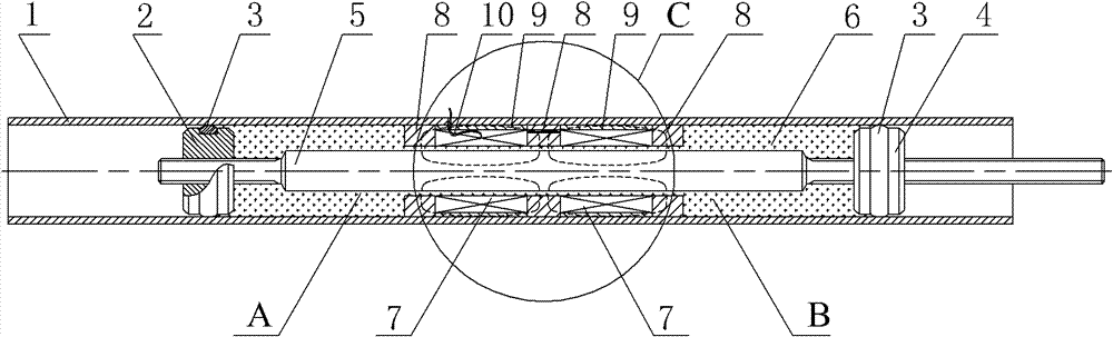
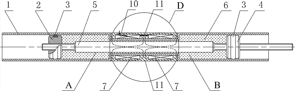
[0018] Specific implementation mode one: combine figure 1 with Figure 8 Describe this embodiment, the compact and lightweight dual-piston magnetorheological damper of this embodiment includes an outer casing 1, a first dynamic sealing piston 2, a second dynamic sealing piston 4, a connecting rod 5, a magnetorheological fluid 6, Two excitation coils 7, three magnetic circuit rings 8 and two outer ring sleeves 9; the first dynamic sealing piston 2, three magnetic circuit rings 8 and the second dynamic sealing piston 4 are sequentially arranged on the outer sleeve 1 from left to right Inside, the first dynamic sealing piston 2 and the second dynamic sealing piston 4 are in sealing and sliding connection with the inner wall of the outer casing 1, the first dynamic sealing piston 2 and the second dynamic sealing piston 4 are connected by a connecting rod 5, and three magnetic circuit rings 8 Fixed in the outer sleeve 1, an excitation coil 7 is installed between two adjacent magne...

specific Embodiment approach 2

[0029] Specific implementation mode two: combination figure 1 The present embodiment will be described. The exciting coil 7 of the present embodiment is a single-stage coil or a multi-stage coil. The case of a single-stage coil is suitable for a relatively small damping force required by the controlled load or structure. The case of multi-stage coils is applicable when the controlled load or structure requires relatively large damping force. Other compositions and connections are the same as in the first embodiment.

specific Embodiment approach 3

[0030] Specific implementation mode three: combination figure 1 To describe this embodiment, the lightweight non-magnetic material of this embodiment is aluminum alloy, magnesium alloy, titanium or polytetrafluoroethylene. Other compositions and connections are the same as those in Embodiment 1 or Embodiment 2.


PUM


Abstract

The invention discloses a compact light-weight double-piston magnetorheological damper, which relates to a magnetorheological damper and is used for solving the problems of large structural size and large weight of the conventional magnetorheological damper. In a scheme I, a first dynamic seal piston, three magnetic loop rings and a second dynamic seal piston are arranged in an outer bushing in sequence from left to right; the two dynamic seal pistons are connected with each other through a connecting rod; an excitation coil is arranged between the two magnetic loop rings, and is fixed between the two magnetic loop rings through an outer ring sleeve; a magnetorheological cavity is formed among the outer bushing, the first dynamic seal piston and the second dynamic seal piston, and is filled with a magnetorheological fluid; and an annular throttling channel is formed between the inner end faces of the magnetic loop rings and the excitation coil and the outer cylindrical surface of the connecting rod. The difference between a scheme II and the scheme I is that: an annular throttling channel is formed between the outer cylindrical surface of the connecting rod and the inner end face of a U-shaped annular groove bottom plate. The magnetorheological damper is particularly suitable for small-load mass vibration isolation and semi-active vibration control over a light structure.

Description

technical field [0001] The invention relates to a magnetorheological damper, in particular to a compact and lightweight dual-piston magnetorheological damper. Background technique [0002] Magnetorheological fluid is an intelligent material whose rheological properties such as viscosity and plasticity change drastically under the action of an external magnetic field. Its basic feature is that it can transform from a free-flowing liquid to a semi-solid within a few milliseconds under the action of an external magnetic field, showing a controllable yield strength, and this change is reversible. The shear yield stress of magnetorheological fluid is an order of magnitude larger than that of electrorheological fluid, and magnetorheological fluid has good dynamic characteristics, low supply voltage and good temperature stability. [0003] The magnetorheological damper is a semi-active control device with excellent performance made of magnetorheological fluid. It has simple struct...

Claims


Application Information

Patent Timeline
Patent Type & Authority Patents(China)
IPC IPC(8): F16F9/53
Inventor 陈照波王强迈迪・阿马迪安
Owner HARBIN INST OF TECH
Why Eureka
Try Eureka