

Passive emergency cooling system for severe accident in reactor
A serious accident and emergency cooling technology, applied in reactors, cooling devices, nuclear power generation, etc., can solve problems such as destruction, failure of the core pressure vessel, containment cooling system, and difficulty in long-term cooling of the water injection tank, and achieve a reasonable valve arrangement. Effect
- Summary
- Abstract
- Description
- Claims
- Application Information
AI Technical Summary
Problems solved by technology
Method used
Image

Examples
Embodiment 1
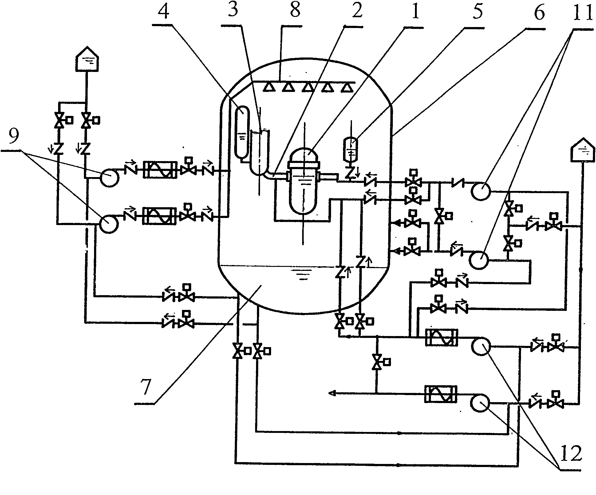
[0026] Such as image 3 Shown, the present invention is made of following equipment:
[0027] 1-water supply pump for high-level pool; 2a-2g-passive control valve group, except for 2C, which is a high-temperature and high-pressure shuttle-type welded check valve, the others are shuttle-type micro-stop return valves, 3-port for mobile pumps; 4-water supply for high-level pools 5-high water pool; 6-core pressure vessel cooling; 7-containment outer roof truss; 8-steel containment shell cooling; 9a-9c-pollution pool cover; 10a-10c-contamination pool water absorber; -light pollution treatment device; 12-moderate pollution treatment device; 13-severe pollution treatment device; 14a-14c-booster pump; 15-passive external containment sprinkler; 16-passive supercharger; H 1 - The submerged water level in the containment vessel is 1; H 2 - submerged water level 2 in containment; 90, 90a - passive main water supply pipe; 100 - return pipe after water treatment
[0028] The passive core...
Embodiment 2
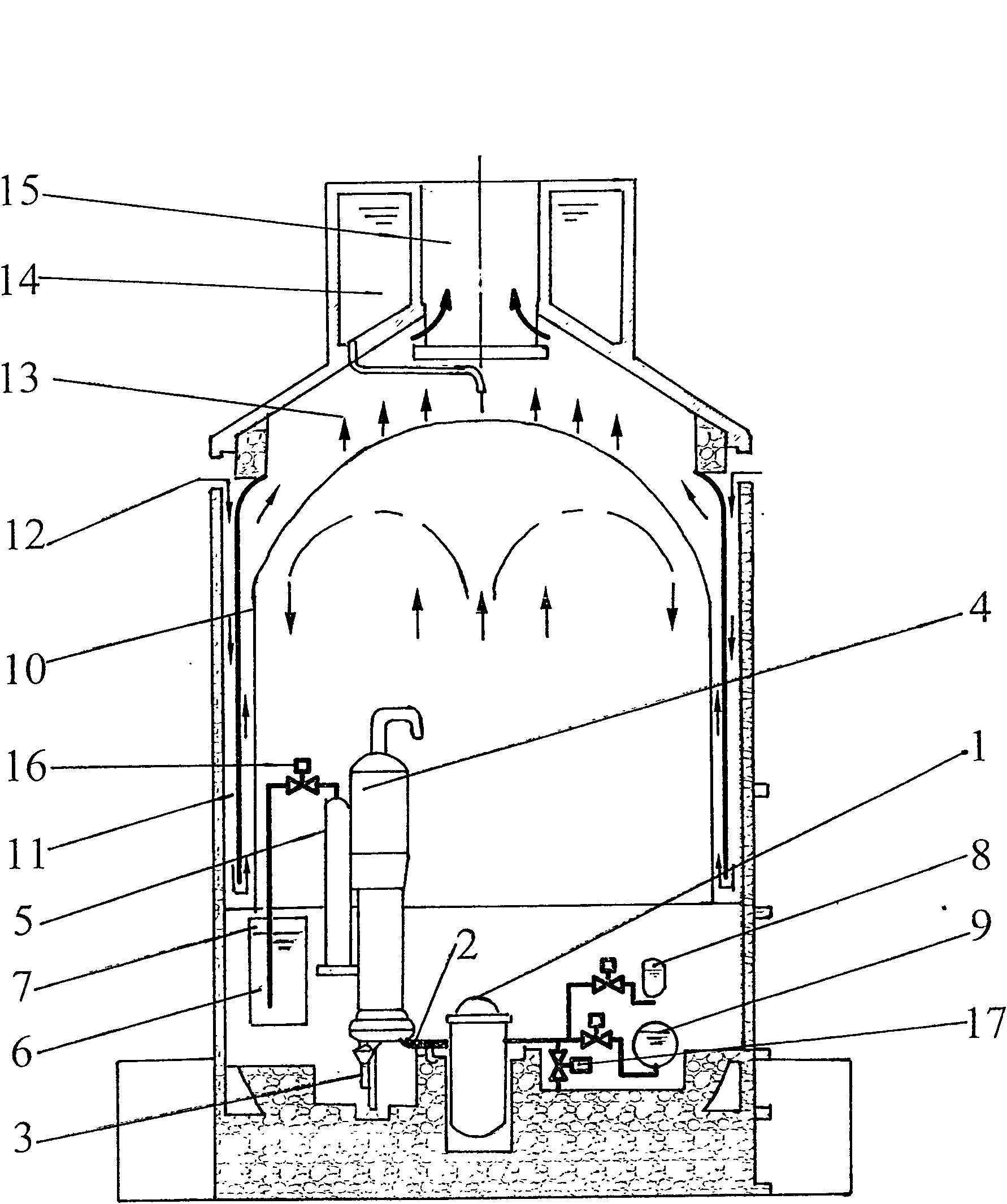
[0078] The connection between the present invention and prior art 2 is as Figure 5 As shown, including the following equipment:
[0079] 1-core pressure vessel; 2-core coolant system; 3-core coolant pump; 4-evaporator; 5-pressure regulator; 6-passive waste heat removal exchanger; 7-refueling water tank; 8 -core makeup water tank; 9-safety water injection tank; 10-steel containment container; 11-deflector; 12-external cooling air inlet; 13-water film evaporation; 14-PCS gravity water tank; 15-natural convection air Exit, 16- Add passive outer containment sprinkler
[0080] Parts 63, 73, 67, 77 and 91 are passive shuttle type micro-resistance or shuttle check valves, and parts 83 and 85 are high temperature and high pressure shuttle type welded check valves.
[0081] Parts 61, 71, 81, 66, 76, 88, and 88a are electric, manual, robot, remote control, and on-site control shut-off valves, which are normally closed when the reactor is in normal operation.
[0082] Parts 62, 72, 8...
PUM
 Abstract
Description
Claims
Application Information