Circuit structure for reading orthogonal rotating current of Hall sensor

A Hall sensor and circuit structure technology, applied in logic circuits, electrical components, reliability improvement and modification, etc., can solve problems such as sensor signal interference, offset voltage cancellation, amplifier offset and noise

Inactive Publication Date: 2012-04-25
HUNAN SEEKSUNS OPTOELECTRONICS TECH
View PDF4 Cites 8 Cited by
  • Summary
  • Abstract
  • Description
  • Claims
  • Application Information

AI Technical Summary

Problems solved by technology

But the disadvantage of this method is that when mass production is carried out, due to the discreteness of the process, even if the consistency of shape and position is paid attention to, the characteristics of each Hall plate will be different, so the offset voltage cannot be completely determined. offset
In addition, sin

Method used


Image

  • Circuit structure for reading orthogonal rotating current of Hall sensor
  • Circuit structure for reading orthogonal rotating current of Hall sensor
  • Circuit structure for reading orthogonal rotating current of Hall sensor

Examples


Example Embodiment

[0010] The present invention will be further described in detail below in conjunction with the drawings and specific embodiments:

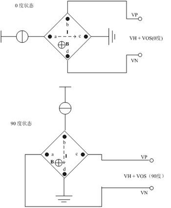
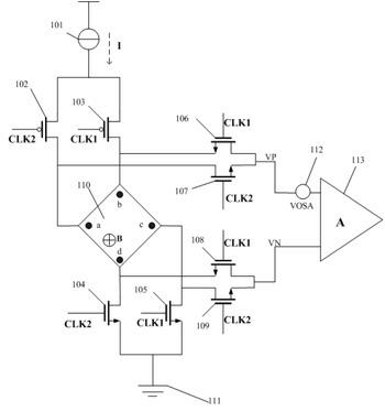
[0011] Such as image 3 As shown, a circuit structure for orthogonal rotating current readout of a Hall sensor includes a constant current source 101, two PMOS switches (102, 103), and six NMOS switches (104, 105, 106, 107, 108). , 109), an amplifier 113 and a square Hall plate 110, and the ground 111, 112 are the equivalent input offset and noise source of the amplifier 113 (defined as VOSA). The said eight MOS switches need to provide two-phase non-overlapping clocks for the selection operation of the switches. The square Hall plate 110 has a terminal at its four corners, which is connected with two PMOS switches (102, 103) and two NMOS switches (104, 105). ) Are connected to each other, the constant current source 101 is connected to the other end of the two PMOS switches (102, 103), and the current is injected from it into the square Hall plate 1...


PUM


Abstract

The invention discloses a circuit structure for reading the orthogonal rotating current of a Hall sensor. The circuit structure comprises a constant current source, six N-channel metal oxide semiconductor (NMOS) switches, two P-channel metal oxide semiconductor (PMOS) switches, an amplifier and a square Hall disk, wherein the eight MOS switches can perform on/off selecting operation by providing two clocks which are not overlapped with each other; the square Hall disk leads out a terminal from four corners respectively; the terminals are connected with two PMOS switches and two NMOS switches respectively; the constant current source is connected with the other end of each of the two PMOS switches respectively; two ends of the residual four NMOS switches are connected with the four terminals of the Hall disk and two input ends of the amplifier respectively; and the generated Hall voltage signal is amplified by the amplifier. By the circuit structure, the offset voltage and noise can be combined with input offset and noise of the back-end amplifier, so that the next level of signal processing circuit can eliminate the offset voltage and the noise conveniently.

Description

technical field [0001] The invention relates to a circuit structure for Hall sensor current readout, more specifically a circuit structure for Hall sensor orthogonal rotation current readout. Background technique [0002] For the CMOS Hall sensor integrated circuit using the Hall plate structure, the influence of non-ideal factors such as the offset voltage of the Hall plate itself, temperature drift, and the noise of the CMOS process itself (such as 1 / f noise) will greatly reduce the impact of the sensor itself on the sensor. Sensitivity to magnetic field. Among them, the offset voltage of the Hall plate itself plays a major role. A common solution is to connect two or more Hall plates in parallel, but let the current directions injected into each other be perpendicular to each other. The offset voltage is canceled because changing the direction of the current only affects the polarity of the Hall plate's offset voltage, not the output signal voltage. But the disadvantag...

Claims


Application Information

Patent Timeline
IPC IPC(8): H03K19/094H03K19/003
Inventor 郭晓雷金湘亮夏宇张成彬
Owner HUNAN SEEKSUNS OPTOELECTRONICS TECH
Why Eureka
Try Eureka