
Jig for holding thin cylindrical work, method for processing thin cylindrical work, and sheet film forming roll

A thin-walled cylinder and holding fixture technology, applied in workpiece clamping devices, workpieces, manufacturing tools, etc., can solve problems such as difficulty in maintaining machining accuracy, deformation of elastic parts, and inability to meet machining expectations, and achieve the effect of improving cylindricity

Inactive Publication Date: 2012-04-25
TOSHIBA MASCH CO LTD
View PDF6 Cites 16 Cited by
  • Summary
  • Abstract
  • Description
  • Claims
  • Application Information

AI Technical Summary

Problems solved by technology

[0012] However, if an elastic member made of a soft material such as rubber is interposed between the workpiece and the holding member, there is a high possibility that the elastic member will be deformed by the pressure during processing, so there is a problem that it cannot meet strict processing expectations.
In addition, when the elastic members are arranged alternately with the spacers, since the parts supporting the inner circumference of the workpiece are intermittent, the elastic members are likely to be further deformed by the pressure during processing, and there is a possibility that they cannot sufficiently respond to severe processing. expected question
For example, in the case of processing thin-walled rolls for extrusion molding, recently it is necessary to finish the outer peripheral surface of the workpiece at the level of micron (cylindricity) and submicron (surface roughness), and it is difficult to maintain the desired Possibility of machining accuracy

Method used


Image

  • Jig for holding thin cylindrical work, method for processing thin cylindrical work, and sheet film forming roll
  • Jig for holding thin cylindrical work, method for processing thin cylindrical work, and sheet film forming roll
  • Jig for holding thin cylindrical work, method for processing thin cylindrical work, and sheet film forming roll

Examples


no. 1 approach

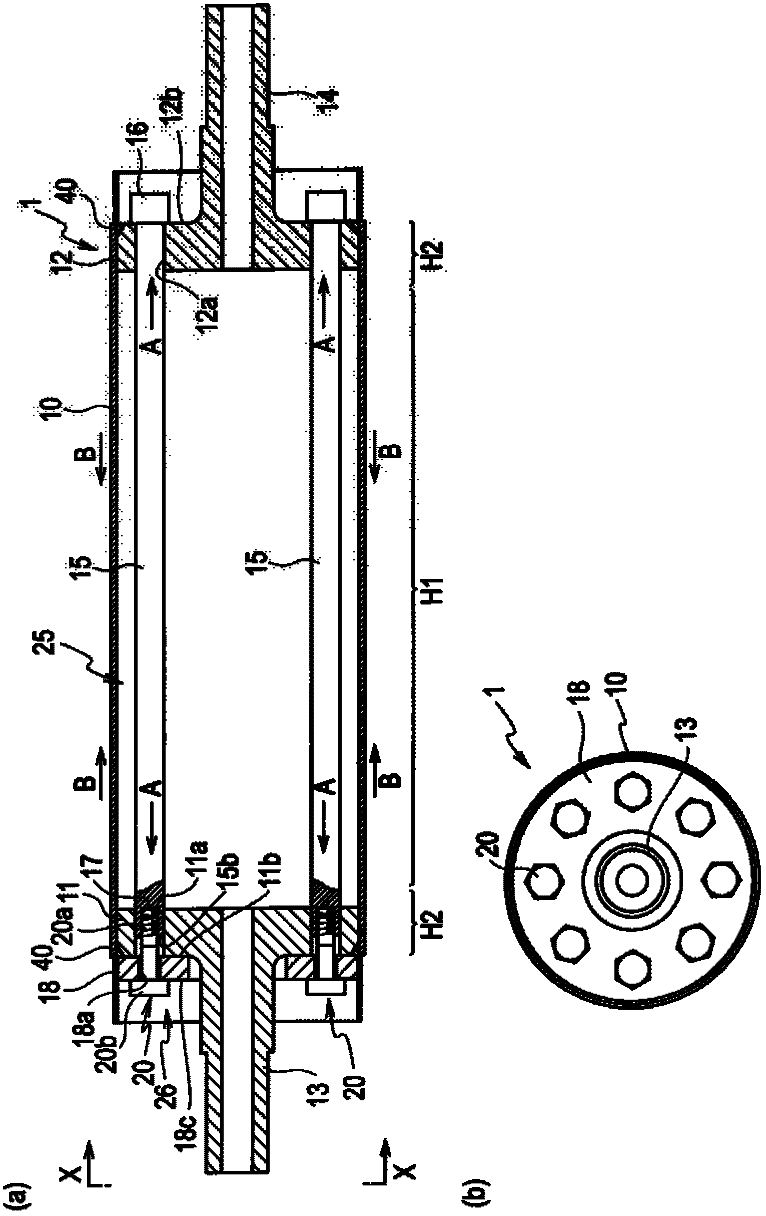
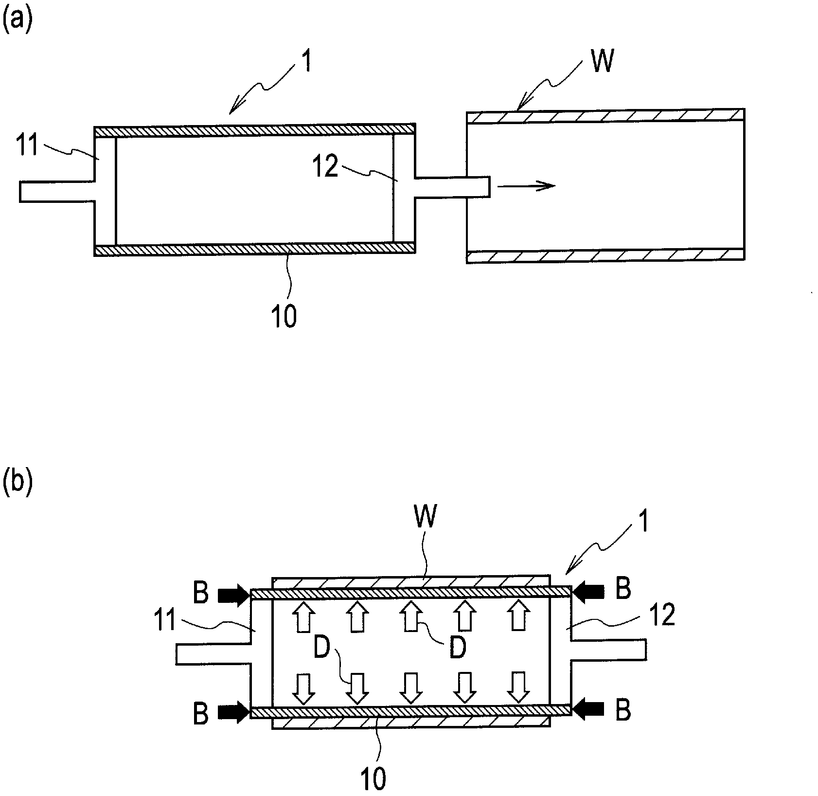
[0047] figure 1 The holding jig 1 shown in (a) and (b) is used for thin-walled cylindrical workpiece W (refer to figure 2 ) is mainly inserted into the inner circumference of the workpiece W when the outer peripheral surface is machined, and the workpiece W is held from the inner peripheral side.

[0048] The workpiece W assumed here is, for example, a sleeve (metal outer cylinder) for forming rolls such as plastic films, and is processed so that the thickness (wall thickness) of the surrounding wall is 2mm or less (more precisely, less than 2mm), and the cylindricity Workpieces of products whose maximum roughness Rmax of the outer peripheral surface is below 50 μm and below 1 μm. The form of use is to use the workpiece W as an outer cylinder, arrange an inner cylinder member coaxially on the inner peripheral side, and ensure a space for the heat medium to flow between the inner cylinder member and the outer cylinder. A forming roll with a double cylinder structure, as requi...

no. 2 approach

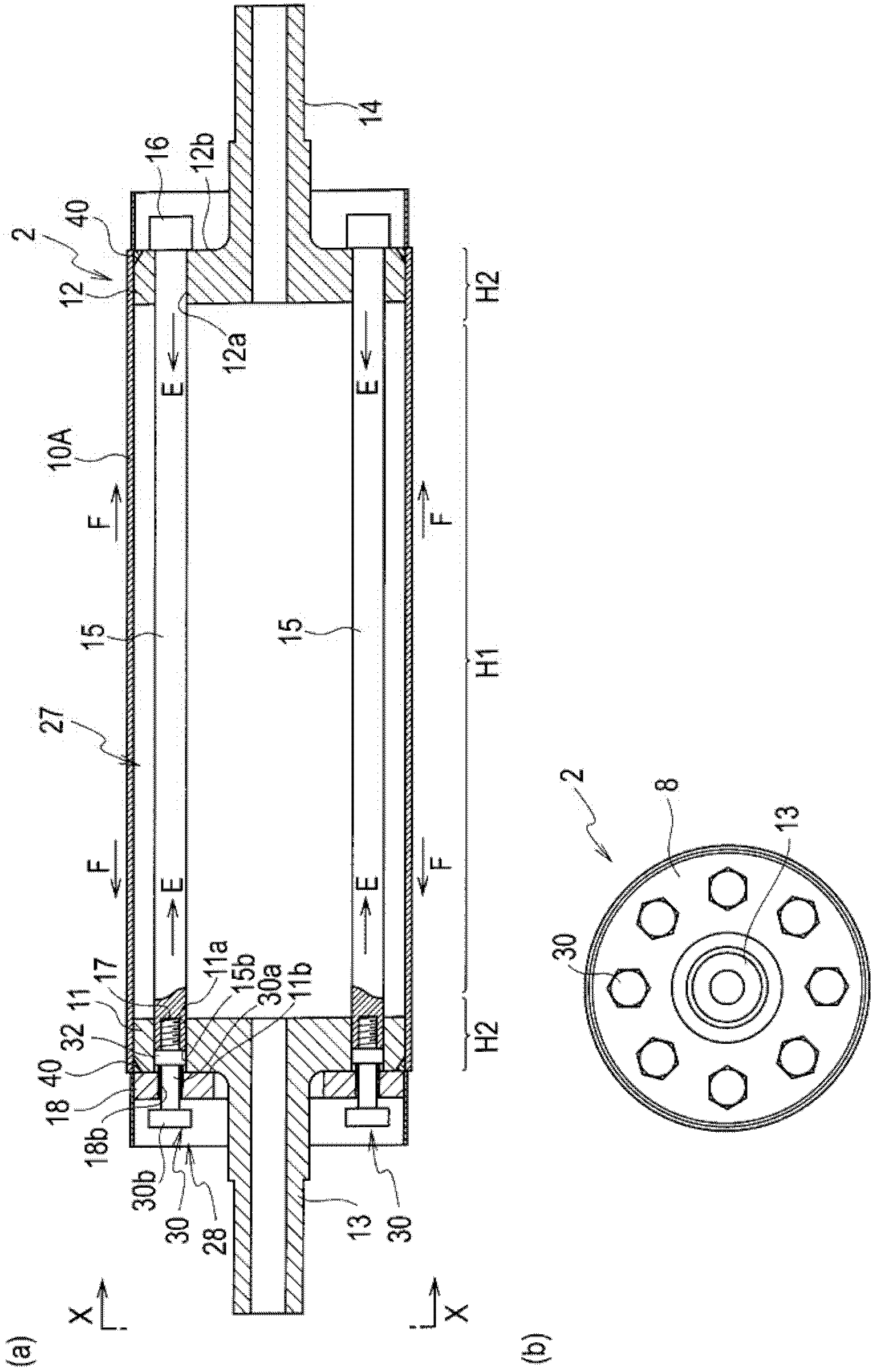
[0064] image 3 The holding jig 2 according to the second embodiment shown in (a) and (b) is also the same as the first embodiment, and is used for thin-walled cylindrical workpiece W (refer to Figure 4 ) is mainly a holding jig 2 that is inserted into the inner periphery of the workpiece W and holds the workpiece W from the inner peripheral side when the outer peripheral surface is machined.

[0065] The holding jig 2 includes a hollow cylindrical metal cylindrical holding member 10A (holding member) whose diameter can be slightly elastically expanded and contracted, and whose wall thickness is set thin. There are shaft portions 13, 14 concentric with the metal cylinder holding member 10A, and a pair of left and right circular side plates 11, 12 that fasten the outer peripheries to both axial ends of the metal cylinder holding member 10A , is disposed between these pair of side plates 11, 12, and the metal cylinder is made A diameter reduction mechanism (diameter changing ...


PUM

PropertyMeasurementUnit
Thicknessaaaaaaaaaa
Thicknessaaaaaaaaaa
Maximum roughnessaaaaaaaaaa

Abstract

A holding jig (1, 2, 3) for a thin cylindrical work (W) includes a holding member (10, 10A, 10B) which holds the work (W) from an inner peripheral side and a diameter changing unit (25, 27) which changes a diameter of the holding member (10, 10A, 10B). The holding member (10, 10A, 10B) is made of metal and has a cylindrical shape and an elastically expandable or contractible diameter. The holding member (10, 10A, 10B) is configured with an outside diameter of the holding member (10, 10A, 10B) being held smaller than an inside diameter of the work (W) at the time of insertion into an inner periphery of the work (W) and being expanded after inserted into the inner periphery of the work (W) to hold the work (W) from an inner peripheral side of the work (W) with an outer peripheral surface in close contact with an entire inner peripheral surface of the work (W). The diameter changing unit (25, 27) applies at least one of an axial external force in a compressing direction or an axial external force in a tensile direction to both ends of the holding member (10. 10A, 10B) to change the diameter of the holding member (10, 10A, 10B).

Description

technical field [0001] The present invention relates to a holding jig for a thin-walled cylindrical workpiece used when machining a thin-walled cylindrical workpiece, a processing method using the holding jig, and a sheet / film forming roll. Background technique [0002] As one of the forming rolls for forming plastic sheets, films, etc., as described in Patent Document 1, it is known that in the inside of a flexible thin-walled metal outer cylinder, through the circulation space of the cooling medium, it is connected with the above-mentioned thin-walled metal outer cylinder. Forming rolls with a double-tube structure in which a high-rigidity metal inner tube is arranged coaxially on the tube. [0003] In Patent Document 1, the wall thickness of the thin-walled cylindrical body used as the thin-walled metal outer cylinder of such a forming roll is an extremely practical range, with an upper limit of 5 mm and a lower limit of 2 mm due to constraints during machining. [0004]...

Claims


Application Information

Patent Timeline
IPC IPC(8): B23B31/40B23Q3/06
CPCB23B31/40B23Q3/064B23B2260/124B23B2215/64B23B2270/06B23B2260/016B23B31/42Y10T29/49544Y10T29/4956Y10T29/49998Y10T29/53961Y10T279/1016Y10T279/1066Y10T279/1087B23Q3/06B25B11/00B23B31/4093
Inventor 佐野孝义古屋忠正
Owner TOSHIBA MASCH CO LTD
Learn More