Radial piston rolling ball type end face valve low-speed high-torque hydraulic motor

A rolling ball, end face technology, applied in the motor field, can solve the problems of inconvenient installation, space limitation, application field and scope restriction, etc., and achieve the effect of stable work, good contact and light weight

Inactive Publication Date: 2012-05-02
YANSHAN UNIV
View PDF4 Cites 11 Cited by
  • Summary
  • Abstract
  • Description
  • Claims
  • Application Information

AI Technical Summary

Problems solved by technology

Water hydraulic axial piston motors and water hydraulic vane motors are high-speed and low-torque motors, and their application fields and scope are inevitably re

Method used


Image

  • Radial piston rolling ball type end face valve low-speed high-torque hydraulic motor
  • Radial piston rolling ball type end face valve low-speed high-torque hydraulic motor
  • Radial piston rolling ball type end face valve low-speed high-torque hydraulic motor

Examples


Embodiment 1

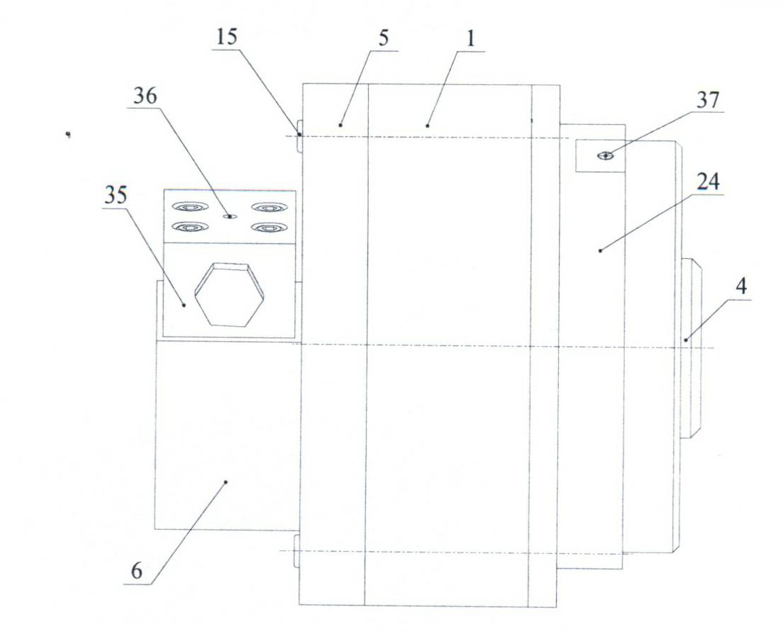
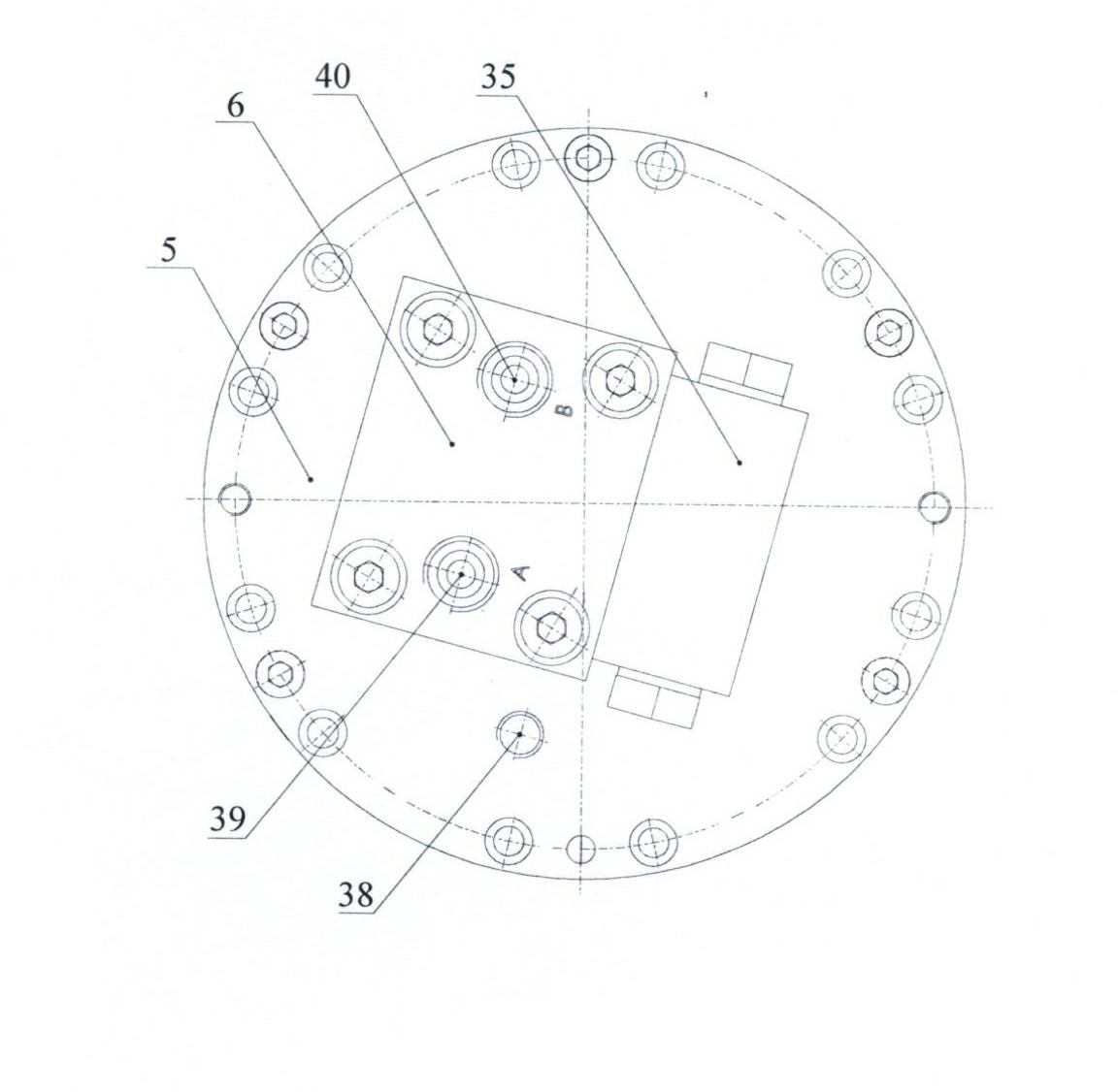
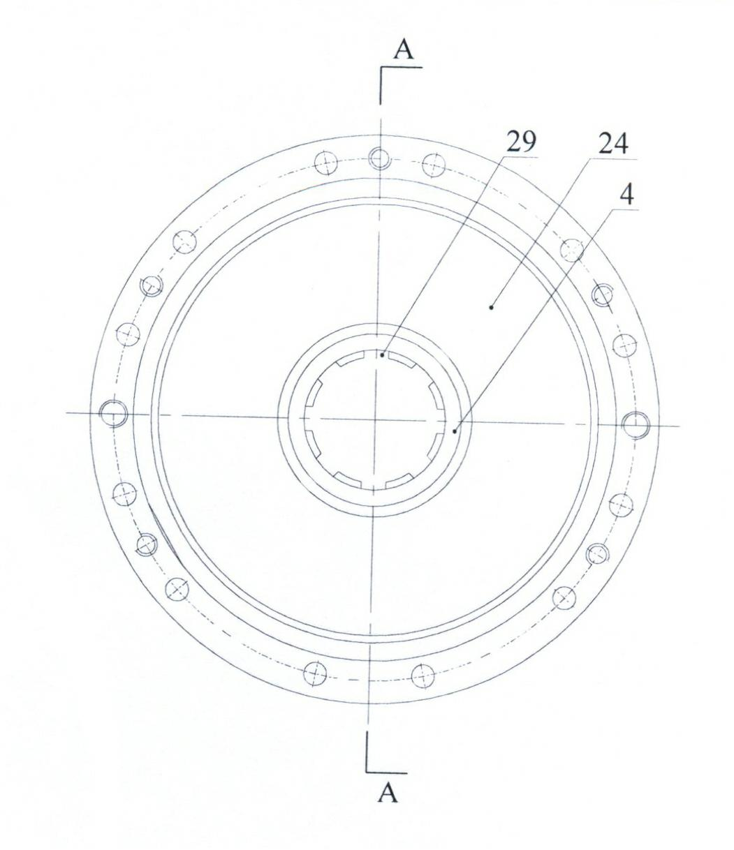
[0063] like figure 1 , figure 2 , image 3 and Figure 4 As shown, a radial piston rolling ball hydraulic motor with an end face distribution pair includes a water block 6, a shuttle valve 35, a flow distribution plate 5, a rotor 4, a stator 1, a thrust ring 22, a right end cover 24, and a shuttle valve 35 It is fixed on the waterway block 6 by four bolts 8, the waterway block 6 is fixed on the distribution plate 5 by four bolts 9, and the rotor 4 is installed on the protruding shaft of the flow distribution plate 5. After assembly, the supporting shaft and the rotor 4 will form a A cavity 31, the thrust ring 22 is installed between the rotor 4 and the right end cover 24, the right end cover 24 has four rectangular slots 59, and the thrust ring 22 has four rectangular keys 55, which can be restricted after being put in. Rotate in the axial direction, the bolt 15 connects the distribution plate 5, the stator 1 and the right end cover 24 to form a whole, add a lip seal ring ...

Embodiment 2

[0077] Such as 32, Figure 33 and Figure 34 As shown in the figure, a radial piston rolling ball hydraulic motor with an end surface distribution pair includes a water block 6, a shuttle valve 35, a flow distribution plate 5', a rotor 4', a stator 1, a thrust ring 22, and a right end cover 24, except Except for the distribution plate 5' and the rotor 4', the structure and assembly of the remaining parts are the same as those in Embodiment 1; Figure 35-Figure 42As shown, the end surface of the distribution plate 5' is an arc surface, and the end surface of the rotor 4' is an arc surface. On the inner end surface of the flow distribution plate 5', there are six evenly distributed inner semicircular rectangular grooves 41 along the radial direction to the center of the circle. Each inner semicircular rectangular groove 41 communicates with the annular flow channel 45 on the end face, and six uniformly distributed outer semicircular rectangular grooves 43 are opened on the inne...


PUM


Abstract

The invention relates to a radial piston rolling ball type hydraulic motor in an end face valve pair. The hydraulic motor comprises a waterway block 6, a shuttle valve 35, a valve plate 5, a rotor 4, a stator 1, a piston 3, a rolling ball 2, a thrust ring 22, a lip-shaped sealing ring 26 and a right end cover 24, wherein the shuttle valve 35 is arranged on the waterway block 6; the waterway block 6 is arranged on the valve plate 5; the rotor 4 is arranged on an extending shaft of the valve plate 5; the thrust ring 22 is arranged between the rotor 4 and the right end cover 24; the valve plate 5, the stator 1 and the right end cover 24 are assembled into a whole; and an inner curved surface 18 of the stator 1 has a compound curve structure which is combined with Archimedes spiral according to constant acceleration, constant deceleration. Due to the adoption of the end face valve, the invention has the characteristics that: the hydraulic motor has a compact structure, fewer friction pairs, light weight, stable work, wide speed regulating range and balanced static force on a supporting shaft, easily realizes low speed and high torque, and the like, and the hydraulic motor is particularly suitable for water hydraulic transmission.

Description

technical field [0001] The invention relates to a motor, in particular to a radial piston rolling ball type end face distribution low-speed high-torque hydraulic motor which uses natural water (including seawater and fresh water) as a hydraulic medium to work. Background technique [0002] The motor is an energy conversion device, which converts the pressure energy of the liquid into mechanical energy. It is the executive element in the hydraulic transmission system and plays an important role in the hydraulic system. The motor with water as the medium has many advantages such as cleanness, no pollution, safety, low cost, high reuse rate, and simple disposal. However, if water is used as the medium, problems such as leakage, wear, and corrosion must be solved, such as friction and wear between friction pairs, corrosion of parts, reduction of leakage and improvement of volumetric efficiency, cavitation, and water click on the question. Judging from the research status and a...

Claims


Application Information

Patent Timeline
IPC IPC(8): F03C2/00
Inventor 高殿荣王志强赵建华张浩费佳欢黄瑶
Owner YANSHAN UNIV
Why Eureka
Try Eureka