High-pressure energy recovering system for urea solution

A technology of energy recovery and high pressure, which is applied in the direction of fluid pressure actuation system components, fluid pressure actuation devices, sustainable manufacturing/processing, etc. It can solve the problem that the recovery efficiency is difficult to exceed 45%, the significance of recovery is not particularly large, and the mechanical loss Large and other problems, to achieve the effect of short energy transmission route, small leakage and high hydraulic efficiency

Inactive Publication Date: 2012-05-02
季裕成
View PDF7 Cites 6 Cited by
  • Summary
  • Abstract
  • Description
  • Claims
  • Application Information

AI Technical Summary

Problems solved by technology

[0007] For fertilizer production, since the medium is mostly in the condition of small flow and high pressure, if the hydraulic turbine unit is also used for energy recovery, due to the low specific speed, the mechanical loss is often quite large, and the recovery efficiency is generally difficult to exceed 45%. ; Moreover, the current domestic hydraulic turbine system is dominated by several big foreign brands, the price is very high, and the recycling significance is not particularly great

Method used


Image

  • High-pressure energy recovering system for urea solution
  • High-pressure energy recovering system for urea solution
  • High-pressure energy recovering system for urea solution

Examples


Embodiment Construction

[0033] The present invention will be further described below in conjunction with the accompanying drawings and specific embodiments.

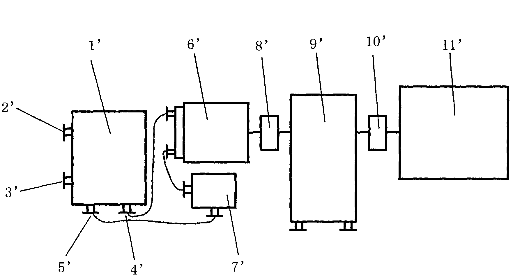
[0034] Such as figure 1 The high-pressure energy recovery system for urea solution shown in , includes a piston exchanger 1', and the piston exchanger 1' has four ports, which are high-pressure liquid inlet 2', high-pressure liquid outlet 3', and hydraulic oil outlet 4' 1. The hydraulic oil inlet 5', the two ports of the hydraulic motor 6' are respectively connected with the hydraulic oil outlet 4' and one port of the hydraulic oil tank 7', and the other port of the hydraulic oil tank 7' is connected with the hydraulic oil inlet 5'. The hydraulic motor 6' is also connected in series with a fluid coupling 8', a high-pressure methyl ammonia pump 9', a clutch 10', and a variable frequency motor 11'.

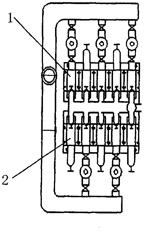
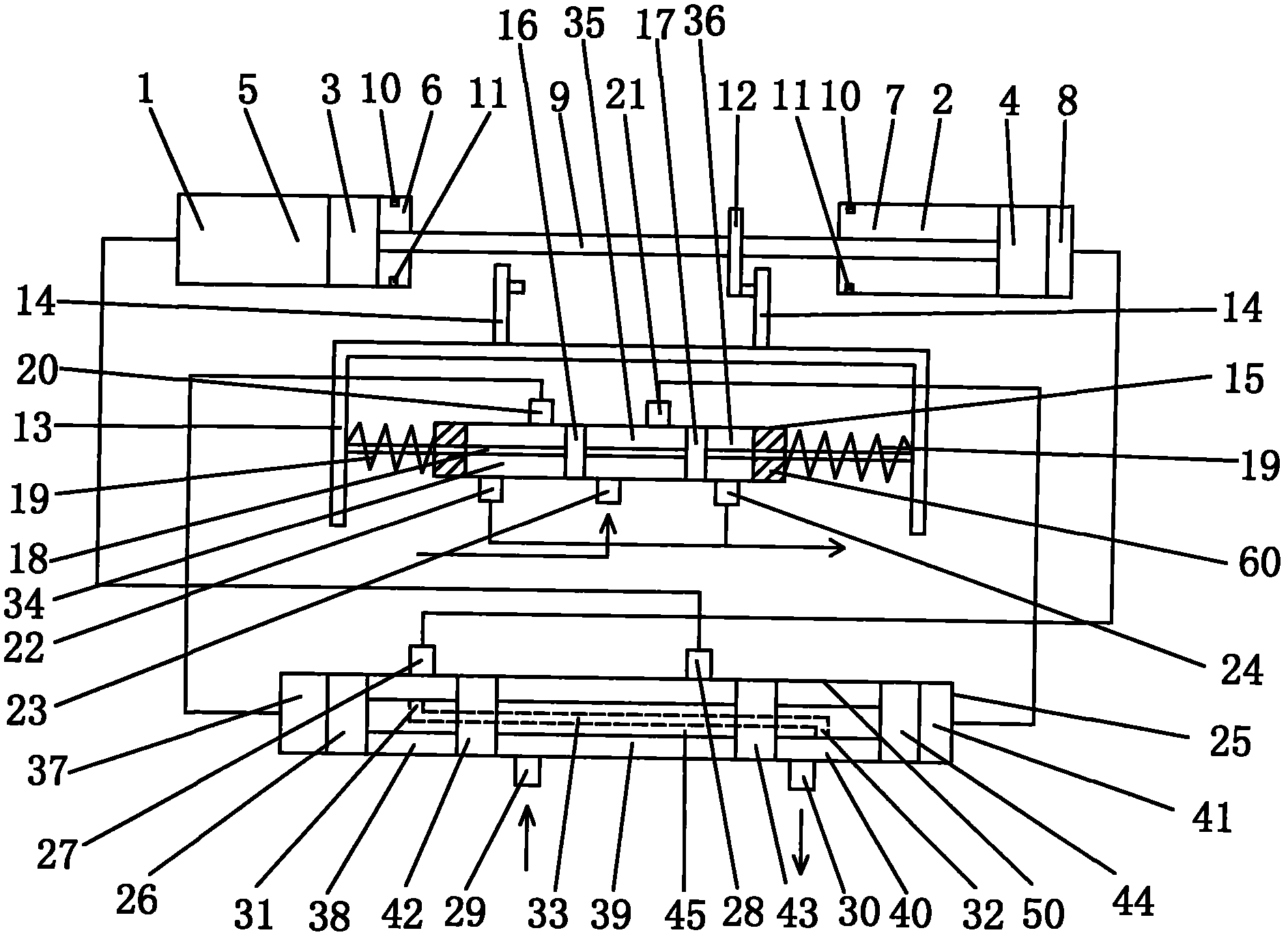
[0035] The piston exchanger 1' is as figure 2 , image 3 As shown in , including 5 pairs of piston cylinders, these 5 pairs of piston cylinders ...


PUM


Abstract

A high-pressure energy recovering system for urea solution is characterized by comprising a piston type exchanger with four ports, namely a high-pressure solution inlet, a high-pressure solution outlet, a hydraulic oil outlet and a hydraulic oil inlet. Two ports of a hydraulic motor are respectively connected with the hydraulic oil outlet and a port of a hydraulic oil tank, and the other port of the hydraulic oil tank is connected with the hydraulic oil inlet. The hydraulic motor is also sequentially connected with a fluid coupling, a high-pressure carbamate pump, a clutch and a variable frequency motor in series. The piston type exchanger comprises five pairs of piston cylinders and a steering system. The energy recovering system is simple in structure and capable of effectively converting high pressure energy generated in the production process of urea into kinetic energy so as to replace electric energy for driving the high-pressure carbamate pump to work normally, thereby saving electricity and reducing production cost.

Description

technical field [0001] The invention relates to a high-pressure energy recovery system, in particular to a high-pressure energy recovery system for urea solution. Background technique [0002] "Energy recovery" refers to the process of converting the energy that has been used into energy that can be used continuously through a specific device. [0003] Many production processes in the petrochemical industry have a large number of fluids with residual pressure. For these high-pressure media, a large part of them are first decompressed to the required low pressure value through a pressure reducing valve, and then the energy is released or re-entered. Process flow, or direct emptying. In the process of decompression and discharge, a large amount of residual pressure energy is converted into heat energy and lost in the environment, causing hundreds of thousands of kilowatts of potential energy to be wasted, which is a pity for the petroleum and chemical industries, which are al...

Claims


Application Information

Patent Timeline
Patent Type & Authority Applications(China)
IPC IPC(8): F15B21/14
CPCY02P20/10Y02P20/141
Inventor 季裕成
Owner 季裕成
Why Eureka
Try Eureka