
Light-emitting diode (LED) cold light source lighting device

A technology for lighting devices and cold light sources, which is applied to lighting devices, components of lighting devices, light sources, etc., can solve problems such as low light energy utilization efficiency, low light energy utilization rate, and difficult assembly, and achieve high light energy utilization efficiency , Mature processing technology and compact structure

Inactive Publication Date: 2012-05-02
HANGZHOU SHOUTIAN PHOTOELECTRIC TECH
View PDF6 Cites 7 Cited by
  • Summary
  • Abstract
  • Description
  • Claims
  • Application Information

AI Technical Summary

Problems solved by technology

[0002] In the application field of optical fiber bundle coupled lighting, such as medical endoscopes, surgical microscopes and other lighting devices, xenon lamps or tungsten halogen lamps are mostly used for lighting at present, which have the disadvantages of bulky, high power consumption, short life, high heat generation, and light energy utilization. Low efficiency and many other disadvantages
[0003] With the rapid development of LED technology, LED lighting devices are gradually being promoted in the above-mentioned application fields. However, the current LED lighting devices mostly use the optical system of reflective bowl and rod mirror, which has low utilization rate of light energy, complicated processing technology and difficult assembly. and other shortcomings

Method used


Image

  • Light-emitting diode (LED) cold light source lighting device
  • Light-emitting diode (LED) cold light source lighting device

Examples


Embodiment Construction

[0010] Further illustrate the present invention below in conjunction with accompanying drawing.

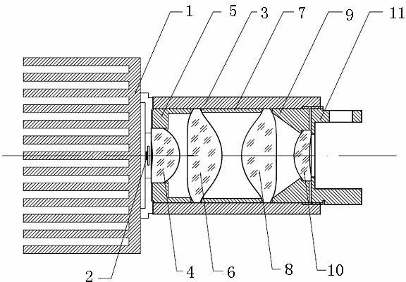
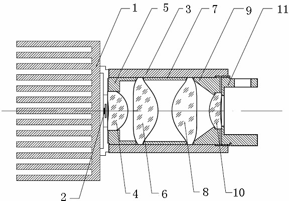
[0011] refer to figure 1 , the LED cold light source lighting device of the present invention comprises an LED chip 2, a heat sink 1 is fixed on one side of the LED chip 2, and a lens barrel 3 is fixed on the other side, and a first lens 4 is sequentially installed in the lens barrel 3 along the outgoing direction of light , the first spacer 5, the second lens 6, the second spacer 7, the third lens 8, the third spacer 9, the fourth lens 10 and the pressure ring 11, the LED chip 2, the first lens 4, the second lens 6. The optical centers of the third lens 8 and the fourth lens 10 are all on the same optical axis, the first lens 4 and the fourth lens 10 are spherical optical glass, and the second lens 6 and the third lens 8 have the same structure on the axis Symmetrical aspheric optical plastic, the second lens 6 and the third lens 8 are placed in opposite directions along the opt...


PUM


Abstract

The invention discloses a light-emitting diode (LED) cold light source lighting device which includes an LED chip. A radiator is fixed on one side of the LED chip, and a lens barrel is fixed on the other side of the LED chip. A first lens, a first space ring, a second lens, a second space ring, a third lens, a third space ring, a fourth lens and a press ring are sequentially disposed in the lens barrel along the emitting direction of light. Optical centers of the LED chip, the first lens, the second lens, the third lens and the fourth lens are all located on an identical optical axis. The first lens and the fourth lens are made of spherical optical glass, and the second lens and the third lens which are in the same structure are made of axially-symmetric aspheric optical plastics and placed along the optical axis in opposite directions. The LED cold light source lighting device has the advantages of being compact in structure, small in volume, high in light energy utilization ratio, developed in processing techniques and more suitable for application field where optical fiber bundle coupling lighting is needed.

Description

technical field [0001] The invention relates to an LED cold light source lighting device, in particular to an LED cold light source lighting device applied to optical fiber bundle coupling lighting. Background technique [0002] In the application field of optical fiber bundle coupled lighting, such as medical endoscopes, surgical microscopes and other lighting devices, xenon lamps or tungsten halogen lamps are mostly used for lighting at present, which have the disadvantages of bulky, high power consumption, short life, high heat generation, and light energy utilization. Low efficiency and many other shortcomings. [0003] With the rapid development of LED technology, LED lighting devices are gradually being promoted in the above-mentioned application fields. However, the current LED lighting devices mostly use the optical system of reflective bowl and rod mirror, which has low utilization rate of light energy, complicated processing technology and difficult assembly. and ...

Claims


Application Information

Patent Timeline
Patent Type & Authority Applications(China)
IPC IPC(8): F21S2/00F21V5/04F21V17/00F21Y101/02
Inventor 王立强
Owner HANGZHOU SHOUTIAN PHOTOELECTRIC TECH
Learn More