Method and rain gauge for measuring rainfall by pulse illumination optics

A measurement method and technology of pulsed light, applied in measuring devices, rainfall/precipitation gauges, meteorology, etc., can solve the problems of not being able to obtain the final falling speed, reducing costs and promoting application barriers, and not being available

Active Publication Date: 2012-05-02
TAIYUAN AERO INSTR
View PDF6 Cites 18 Cited by
  • Summary
  • Abstract
  • Description
  • Claims
  • Application Information

AI Technical Summary

Problems solved by technology

Undoubtedly, the subsequent data collection and processing costs of such a high-speed data flow are very high, which is an obstacle to reducing costs and popularizing applications.
In addition, even if the linear array method is used, it is impossible to obtain the precise final velocity of falling, because what can be obtained is only the degree of time, and the precise geometric size in the vertical direction cannot be obtained, and the precipitation particles are often not spherically symmetrical.
Therefore, the linear array optical rain gauge cannot completely solve the problem of simultaneous measurement of the scale spectrum and terminal velocity spectrum.
[0005] In order to obtain more abundant precipitation particle information, some people have also studied the use of area array optical devices to directly photograph precipitation particles. The full-screen smearing image of particles cannot be clearly imaged
Therefore, we have to resort to high-speed or ultra-high-speed cameras. Obviously, solutions based on high-speed cameras cannot be promoted at low cost.

Method used


Image

  • Method and rain gauge for measuring rainfall by pulse illumination optics
  • Method and rain gauge for measuring rainfall by pulse illumination optics
  • Method and rain gauge for measuring rainfall by pulse illumination optics

Examples


Embodiment Construction

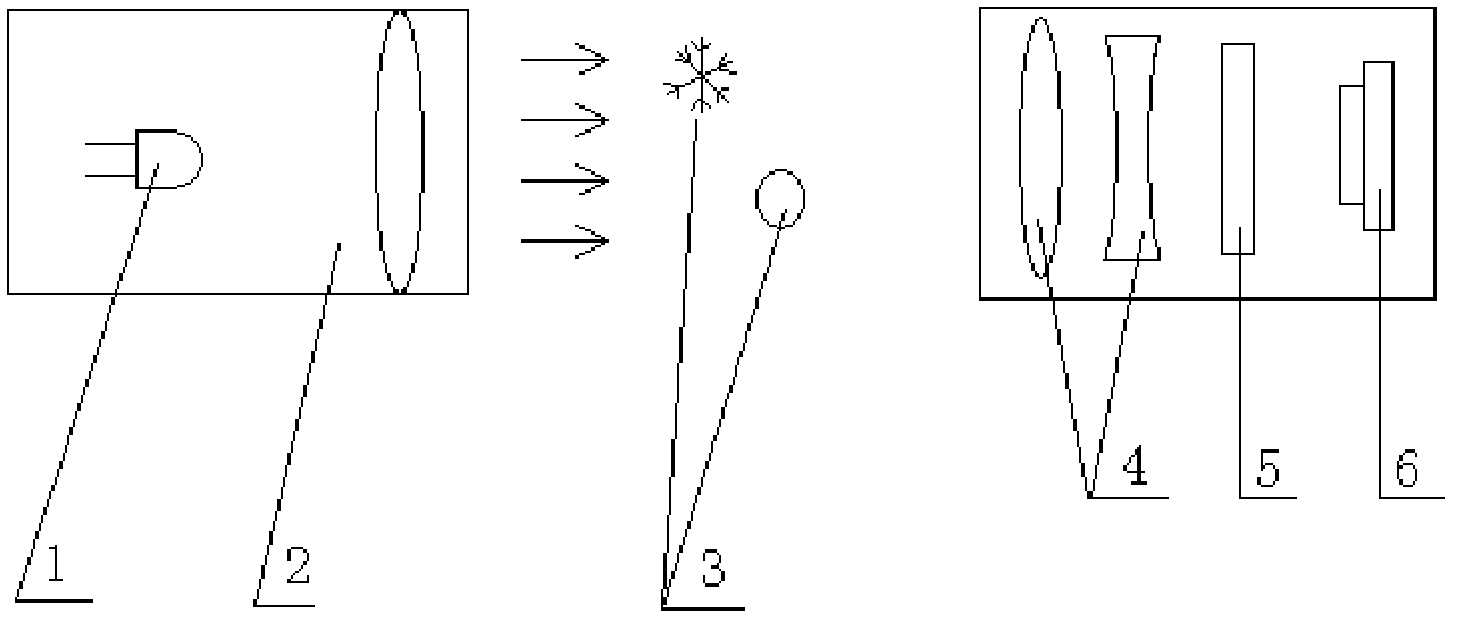
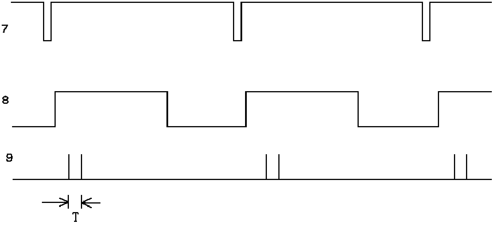
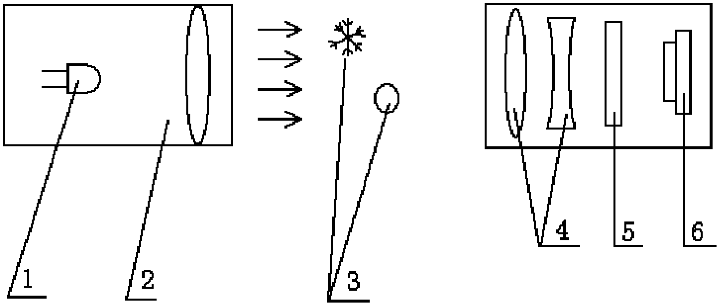
[0011] In the figure, 1 represents a pulse light emitting device; 2 represents a pulsed illumination parallel light source system; 3 represents precipitation particles; 4 represents a receiving optical system; 5 represents a filter matching the wavelength of emitted light; 6 represents a two-dimensional image sensor. figure 2 In the signal waveform diagram, 7 represents the field synchronization signal; 8 represents the electronic shutter signal, and the high level is continuous exposure; 9 represents the pulse lighting control, and each field has two lightings, and the interval is T.

[0012] The optical rain gauge obtained based on the method of the present invention is composed of a pulsed illumination parallel light source system 2 and a two-dimensional image sensor 6 . The pulse light emitting device 1 can be an LED light emitting diode or a semiconductor laser, etc., and the two-dimensional image sensor 6 can be a CCD area array or a CMOS area array. The non-parallel li...


PUM


Abstract

The invention relates to a method for measuring rainfall by pulse illumination optics. According to the method, controllable pulsed light is adopted, the transmission of the controllable pulsed light is consistent with frame synchronizing signals of image video signals, and the pulsed light is transmitted twice at certain time intervals T in each frame of exposure time; actually, each frame of acquired image is acquired by performing double exposure on precipitation particles, the double exposure makes particles appear at two different positions of the same fame of image, and the velocity of the particles is calculated by measuring the distance in which the particles are moved within the time T on each frame of image; the volume of the particles can be calculated according to particle sizes of precipitation particles in a measured clear precipitation particle image, the instantaneous precipitation values can be calculated by combining sampling areas, and the instantaneous rainfall is integrated to acquire gross rainfall; and rain, snow or hail can be identified according to the image of the precipitation particles and parameters such as drop spectrum distribution, velocity and the like. According to the method, particle size and dropping velocity can be simultaneously measured, and the method is extremely economic.

Description

technical field [0001] The invention relates to the field of meteorological precipitation measurement, in particular to a method and equipment for simultaneously measuring precipitation amount, precipitation intensity and precipitation type by optical means. Background technique [0002] Precipitation in the meteorological sense refers to the depth of the water layer that falls to the ground and accumulates without evaporation, infiltration or loss. Precipitation intensity refers to the amount of precipitation per unit time, and precipitation type refers to the classification of weather phenomena of precipitation phenomena, such as: sleet, drizzle, hail, etc. [0003] The rain gauge is a meteorological instrument for measuring the amount of precipitation and precipitation intensity. At present, there are rain gauges, tipping bucket rain gauges, and siphon rain gauges. The rain gauge collects rainwater into the container, and then measures it manually; the tipping bucket rai...

Claims


Application Information

Patent Timeline
Patent Type & Authority Applications(China)
IPC IPC(8): G01W1/14
CPCY02A90/10
Inventor 翟东力
Owner TAIYUAN AERO INSTR
Why Eureka
Try Eureka