Method for etching edges of solar battery

A solar cell, edge technology, applied in circuits, electrical components, sustainable manufacturing/processing, etc., can solve the problems of over-etching, high equipment cost, difficult control, etc., to achieve parallel resistance and fill factor improvement, leakage current The effect of reduced, high parallel resistance

Inactive Publication Date: 2012-05-02
百力达太阳能股份有限公司
View PDF3 Cites 7 Cited by
  • Summary
  • Abstract
  • Description
  • Claims
  • Application Information

AI Technical Summary

Problems solved by technology

However, sulfuric acid must be added to the etching solution in this way to increase the surface tension of the mixed acid, otherwise the acid solution will spread over the diffusion surface, resulting in over-etching
The disadvantage of this method is that the concentration of each component of the acid must be controlled within a precise range, the control is relatively difficult, and the equipment cost is very high
Some domestic models use the method of removing the phosphorosilicate glass first and then etching, which greatly reduces the equipment cost. However, although this method can use the hydrophobic nature of silicon after removing the phosphorosilicate glass to prevent over-etching at the edge, the diffusion surface is exposed in wet It is also obvious that the gas phase corrosion caused by the mixed acid volatile gas causes the uneven sheet resistance, and the uneven sheet resistance has a great negative impact on the stability of the conversion efficiency of solar cells

Method used


Image

  • Method for etching edges of solar battery
  • Method for etching edges of solar battery
  • Method for etching edges of solar battery

Examples


Embodiment Construction

[0010] In order to make the present invention more comprehensible, a preferred embodiment is described in detail below with accompanying drawings.

[0011] The invention provides a solar cell edge etching method, the steps of which are:

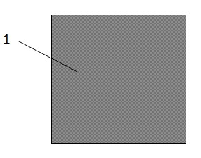
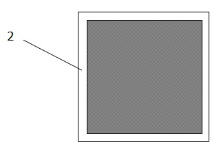
[0012] Step 1, providing a diffused silicon wafer, Figure 1A Shown is a diffused silicon wafer 1 whose surface is covered with dark phosphosilicate glass. Perform a plasma etching on it to remove the phosphosilicate glass around the silicon wafer. Figure 1B Shown is the silicon wafer 2 after plasma etching, and the phosphosilicate glass with a width of 1-2 mm has been etched away around it, exposing the silicon body.

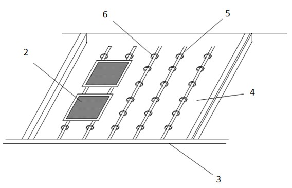
[0013] Step 2, performing wet etching on the silicon wafer after plasma etching according to a conventional process. figure 2 Shown is a typical wet etching tank, the tank body 3 is a part of the wet etching machine, containing etching solution 4, its composition is a mixed solution of nitric acid and hydrofluoric acid, an...


PUM


Abstract

The invention provides a method for etching edges of a solar battery, which is characterized by comprising the following steps that: a diffused silicon chip is provided, primary plasma etching is executed on the diffused silicon chip so as to remove phosphorosilicate glass on the periphery of the diffused silicon chip, and then wet etching is performed on the silicon chip after the plasma etching according to a conventional flow. By adding one time of traditional plasma etching, the phosphorosilicate glass on the periphery of the silicon chip after being diffused can be removed, and the major area on the middle part of the silicon chip is still covered by the phosphorosilicate glass, so the hydrophobic property of the exposed silicon main body on the periphery of the silicon chip is also utilized to prevent the etching liquid from infiltrating the upper surface of the silicon chip. After twice etching, the parallel-connection resistance and the filler factor of cell slice can be remarkably improved, and the drain current can be remarkably reduced. Therefore, the wet etching with low cost, high stability and high parallel-connection resistance can be realized.

Description

technical field [0001] The invention relates to a solar cell manufacturing method, in particular to a solar cell edge etching method, and belongs to the technical field of solar cell production. Background technique [0002] In today's solar cell manufacturing process, the edge etching process generally includes plasma etching, that is, dry etching and wet etching. Dry etching is a mature edge etching technology with simple operation and large production capacity, but it is prone to incomplete etching and cannot achieve backside etching. It has been gradually replaced by wet etching in the manufacture of polycrystalline cells. . The main advantage of wet etching technology is that the silicon wafer is close to floating on the mixed solution of nitric acid and hydrofluoric acid and flows through. Using the surface tension of the liquid, the edge and back of the silicon wafer are corroded, and the corrosion amount of the chemical reaction is lower than that of the silicon waf...

Claims


Application Information

Patent Timeline
Patent Type & Authority Applications(China)
IPC IPC(8): H01L31/18
CPCY02P70/50
Inventor 王锋萍
Owner 百力达太阳能股份有限公司
Why Eureka
Try Eureka