
Piezoelectric energy trapping device

A technology of piezoelectric energy harvesting and piezoelectric bimorphs, which is applied in the direction of electric energy storage systems, electrical components, piezoelectric effect/electrostrictive or magnetostrictive motors, etc., can solve the problem of low electromechanical coupling coefficient and electromechanical energy conversion. Low work efficiency and other problems, to achieve the effect of increasing output power and improving work efficiency

Inactive Publication Date: 2012-05-02
SOUTHEAST UNIV
View PDF5 Cites 6 Cited by
  • Summary
  • Abstract
  • Description
  • Claims
  • Application Information

AI Technical Summary

Problems solved by technology

Since the electromechanical coupling coefficient of the piezoelectric device itself is generally low, the work efficiency of the electromechanical energy conversion of the piezoelectric energy harvesting device is low.

Method used


Image

  • Piezoelectric energy trapping device
  • Piezoelectric energy trapping device
  • Piezoelectric energy trapping device

Examples


Embodiment Construction

[0014] Below in conjunction with accompanying drawing, the technical scheme of invention is described in detail:

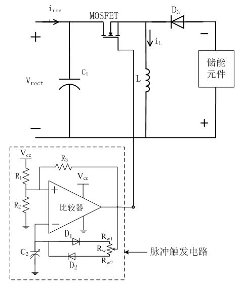
[0015] Such as figure 1 The piezoelectric energy harvesting device shown includes a piezoelectric bimorph cantilever, a rectifier circuit 8 , a DC-DC regulation circuit 9 , an energy storage element 10 , and wires 6 and 7 . A piezoelectric bimorph has piezoelectric layers 3, 4 and an elastic layer 2. The part of the elastic layer 2 beyond the piezoelectric layer is inserted into the base 1, called the fixed end, so as to fix the cantilever beam. The other end of the cantilever beam corresponding to the fixed end is called a free end, and a mass block 5 is fixed at the free end of the cantilever beam. Piezoelectric layers 3, 4 and elastic layer 2 are bonded together by 504 universal adhesive. In order not to affect the conductivity, when bonding, the adhesive layer should be thinner and thinner without affecting the bonding strength. it is good. Metal electrode...


PUM


Abstract

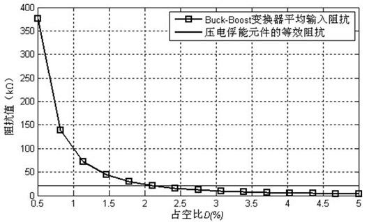
The invention relates to an energy trapping device, in particular to a piezoelectric energy trapping device, which comprises a piezoelectric bimorph cantilever, a rectifying circuit, a direct current (DC)-DC regulation circuit, an energy storage element and a conducting wire, wherein an alternating current which is generated by the piezoelectric bimorph cantilever is converted into a DC through the rectifying circuit; and the DC which is obtained by impedance matching of the DC-DC regulation circuit supplies power to a load. By regulating the duty ratio of a metal oxide semiconductor field effect transistor (MOSFET) in the DC-DC regulation circuit, the average input resistance of a DC converter can be regulated, so that the impedance matching of piezoelectric energy trapping elements is realized, and the output power of the piezoelectric energy trapping device is improved.

Description

technical field [0001] The invention relates to an energy harvesting device, in particular to a piezoelectric energy harvesting device. Background technique [0002] With the advent of the information age, various low-power products such as microelectronics, wireless network sensors and MEMS have been vigorously developed. At present, their main energy supply method is battery, but there are many disadvantages in the battery method, such as limited battery life, It needs to be replaced regularly, and sometimes it is difficult to replace the battery due to environmental restrictions. The environment is rich in low-frequency mechanical vibration energy. If energy can be collected from the surrounding environment, it will be able to provide reliable power supply for micro-power electronic products. The piezoelectric vibration energy harvesting method is widely used in environmental vibration energy due to its high power density, no need for external power supply, no heat gener...

Claims


Application Information

Patent Timeline
Patent Type & Authority Applications(China)
IPC IPC(8): H02N2/00H02J15/00
Inventor 黄学良邹玉炜谭林林
Owner SOUTHEAST UNIV
Learn More