
Hall effect plasma thruster

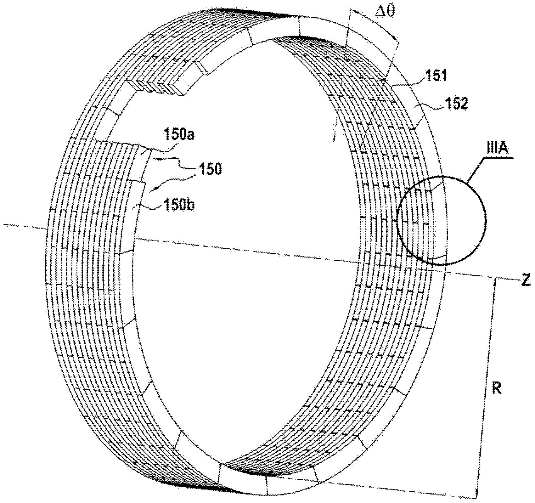
By using a laminated structure of conductors or semiconductor rings and insulating materials in the Hall effect plasma thruster, the discharge channel structure is optimized, the problems of ceramic channel corrosion and efficiency loss are solved, and a thruster with longer life and high efficiency is achieved. performance.

Inactive Publication Date: 2012-05-02
斯奈克码 +3
View PDF0 Cites 15 Cited by
  • Summary
  • Abstract
  • Description
  • Claims
  • Application Information

AI Technical Summary

Problems solved by technology

Boron nitride-based ceramics enable Hall-effect thrusters to achieve good performance levels in terms of efficiency, but their high corrosion rates under ion bombardment limit the lifetime of such thrusters to about 10,000 hours (h) , which also limits their operational performance at the highest specific pulse

Method used


Image

  • Hall effect plasma thruster
  • Hall effect plasma thruster
  • Hall effect plasma thruster

Examples


Embodiment Construction

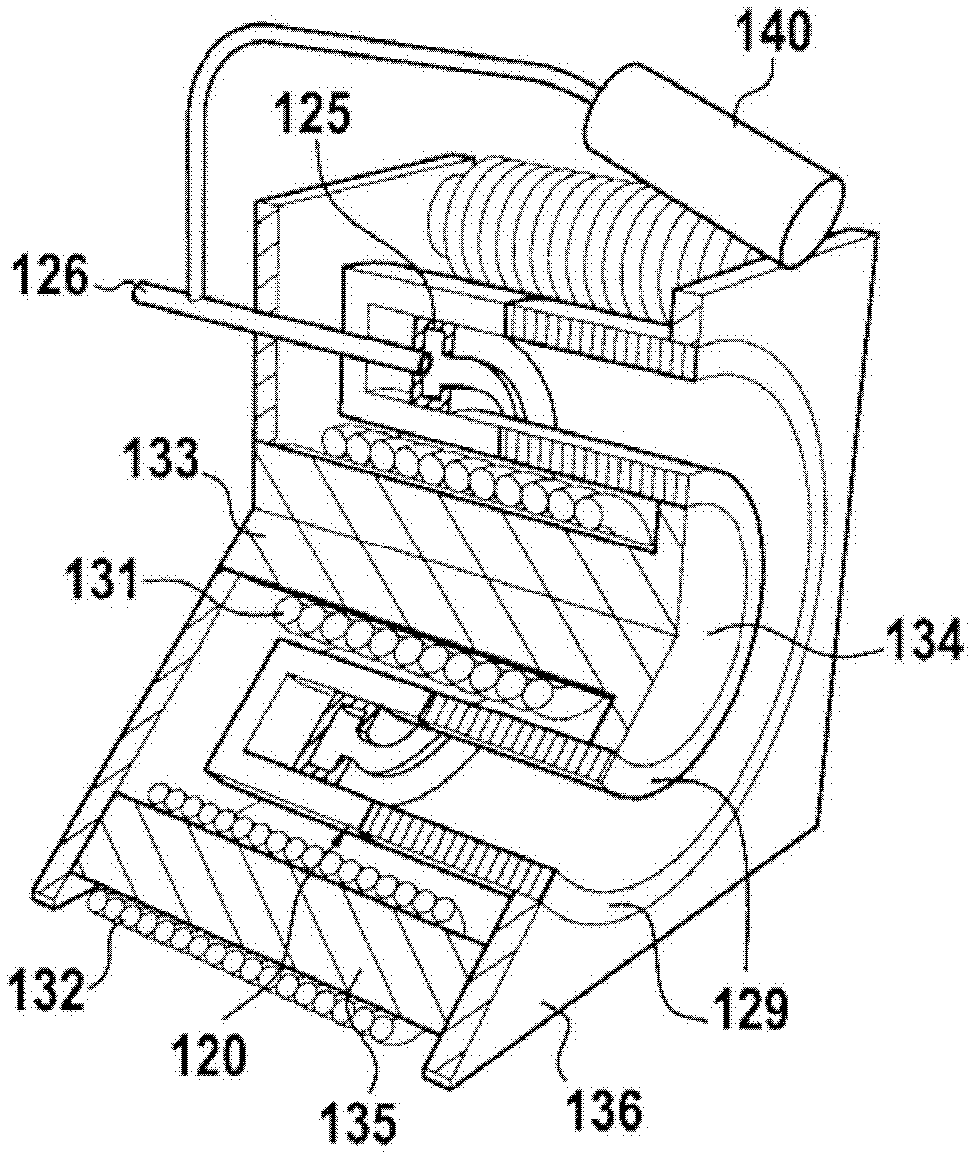
[0037] figure 1 One embodiment of a Hall effect plasma thruster, also known as a stationary plasma thruster (SPT), is shown, where this embodiment of the invention is practicable, particularly for electric propulsion of satellites.

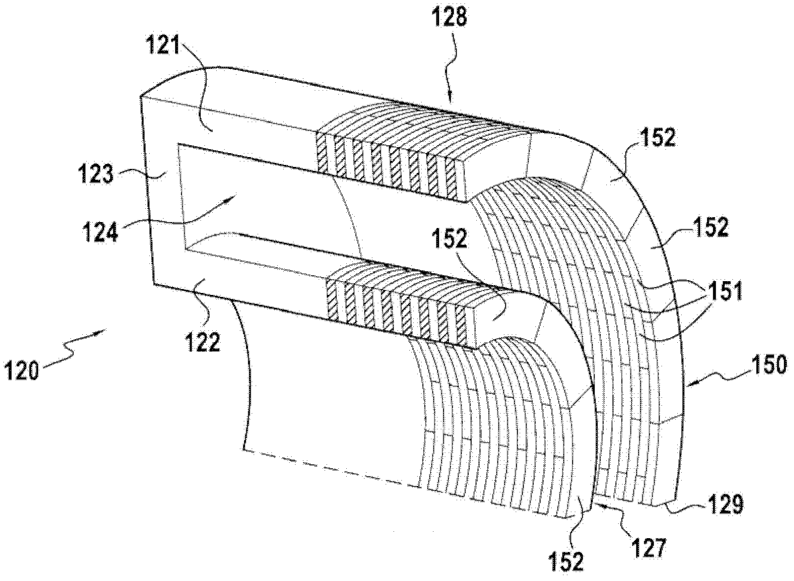
[0038] This type of Hall effect thruster comprises the following main elements: a discharge channel or main annular channel 120 for ionization and acceleration; an annular anode 125 coaxial with said main annular channel 120; connecting said anode 125 to said The main annular channel 120 is a tube 126 and manifold for feeding an ionized gas such as xenon; a hollow cathode 140; and magnetic circuits 131 to 136 for generating a magnetic field in the main annular channel.

[0039] The anode 125 and manifold for ionized gas are intended to inject propellant (eg xenon) into the thruster and to collect electrons released by the plasma.

[0040] The hollow cathode 140 is used to generate electrons, which are used to generate the plasma in the thruster, ...


PUM


Abstract

The invention relates to a Hall effect plasma thruster including a main annular ionization and acceleration channel (120) having an open downstream end (129), at least one cathode, an annular anode that is concentric with the main annular channel (120), a pipe and a dispenser for feeding an ionizable gas into the channel (120), and a magnetic circuit for generating a magnetic field in the main annular channel (120). The main annular channel (120) includes portions of inner (127) and outer (128) annular walls located in the vicinity of the open end and (129) each including an assembly of conductive or semiconducting rings (150) juxtaposed in the form of blades separated by thin layers of insulation (152).

Description

technical field [0001] The present invention provides a Hall effect plasma thruster having a main annular channel for ionization and acceleration and having a downstream open end, at least one cathode, and said main annular channel Concentric annular anodes, tubes and manifolds for feeding ionized gas into the channels and a magnetic circuit for generating a magnetic field in the main annular channels. [0002] In particular, the present invention provides a Hall-effect plasma thruster used for electric propulsion of an artificial satellite. . Background technique [0003] The lifetime of a Hall effect plasma thruster is determined by the corrosion of the ceramic insulating channels under the effect of ion bombardment. Based on the distribution of electric potential in the channel, ions are generated and accelerated towards the wall in radial direction. [0004] The requirement of extending the mission of communication satellites and increasing the velocity of plasma jets...

Claims


Application Information

Patent Timeline
Patent Type & Authority Applications(China)
IPC IPC(8): F03H1/00
CPCF03H1/0075F03H1/0062H01J27/143H05H1/54
Inventor 塞奇·巴拉尔史蒂芬J.·泽巴奇
Owner 斯奈克码
Learn More